I am thankful to Dr. David C. Evans and Dr. Ivan E. Sutherland for the great amount of time and suggestions each of them gave in the development of this algorithm, and for their help given in preparing this dissertation.
Mr. Roy A. Keir has read many drafts of this Dissertation. It has been his consultation that has assisted in making this final dissertation readable and understandable.
To Mr. Michael Archuleta, I am grateful for his capability and help in creating a program for testing the hidden line algorithm.
I am thankful to Dr. Gordon Romney for introducing me to computer graphics, and for the creative times we worked together.
With the increasing use of computer graphics, a need is growing for a processor capable of displaying solid objects. Environmental simulation and architectural modeling are only two areas that would benefit from such a display processor.
This dissertation describes an algorithm designed for such a processor, and a program for simulating the hardware processor. The hardware processor would be capable of generating pictures of fairly complicated objects at thirty frames per second. Statistics describing its simulated performance have been extracted and are reported within the dissertation.
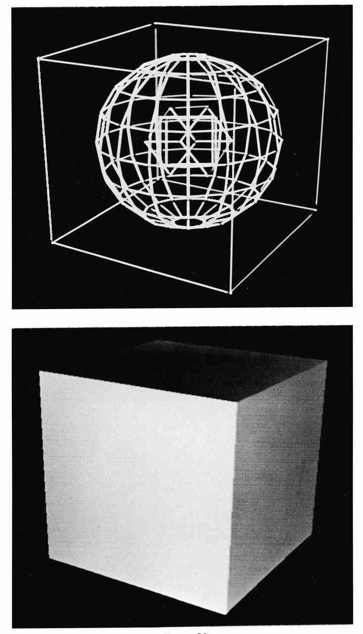
With the introduction of line-drawing displays, it was soon realized that displaying too much information detracted from the meaning and actually confused the picture. For instance, a single cube can create an optical illusion as shown in Figure 1. However, the optical illusion is removed if lines hidden by surfaces in front of them are not displayed (see Figure 2). A different approach could be taken. Instead of determining the hidden lines, an algorithm could find, color, and shade visible surfaces, thus presenting a more true to life picture. For the past several years, different algorithms have been developed for solving the hidden line or visible surface problem. The various algorithms can be classified into several groups.
Some solutions to the problem have been found by various methods of tracing along the edges of objects and noting which of the edges are wholly or partially visible. The resulting picture is then the display of the visible segments of edges. Algorithms based on this method have been developed by Roberts [1], Loutrel [2], and Appel [3]. This type of approach does not take into account the resolution of the display but solves the hidden line problem to the precision inherent in the object description.
In 1967 a paper was presented by Wylie, Romney, Evans, and Erdahl [4]. One of the concepts discussed was initiated by Evans and introduced the concept of a sample space. the concept states that given an output device with resolution of Rx by Ry , one need only solve the hidden line problem at the discrete resolution points. The sample space can be thought of as taking the original object description in X, Y, Z, and mapping the object on to a two dimensional grid of resolution Rx by Ry. Of course, the Z information needs to be preserved in some form. When this is done, the object will exist only at discrete points in X and Y. The reasoning behind this was when a person views a picture he is physically limited by the resolution of the eye and the resolution of the display device. Hence, the hidden line problem need only be solved to the coarser resolution of the two.
In the algorithm, non-intersecting triangles were used as the object description. However, convex polygons could have been used with only small changes in the program. The algorithm used a scan line approach. That is, one Y raster line would be completely solved for visible triangles before the program proceeded to the next scan line. A method of sorting vertices of the triangles was developed by Wylie and Romney so only triangles concerned with the current scan line were considered. On each scan line, triangle depths were compared only where edges of the triangles crossed the current scan line. Therefore, it was not necessary to do depth computations at all raster points. Later Romney [5] improved the sorting technique and added a speedy check to the program to take advantage of scan line-to-scan line coherence. This improved the speed by eliminating depth sorting as long as triangles entering on the scan line were ordered the same as the previous scan line.
Warnock [6] took a new approach but still kept the grid of resolution points. The object description was generalized by allowing polygons (convex or non-convex) which could intersect one another. Instead of the scan line approach, Warnock took an area of the picture and tried to understand it. If it was simple enough to understand he would display it, otherwise he subdivided the area into smaller areas. Eventually, a sub-area could be understood and displayed, or a sub-area would reach resolution whereupon it would be displayed without further analysis. This concept of subdividing large problems into smaller (and easier) problems is a non-deterministic algorithm.
After Warnock's algorithm was developed, Bouknight [7] took the scan line approach and generalized it to include general polygons which could intersect. Figure 3 shows a classification of the various algorithms.
The new algorithm to be described is of the mapped sample space class, and it allows general polygons which can intersect. Key ideas used in this algorithm are: (1) Scan line-to-scan line coherence of pictures, and (2) an arithmetic unit for Z-depth sorting. Frame-to-frame coherence was not found valuable (in terms of increasing the speed of the program) for inclusion in this final algorithm.
The program implementing this algorithm is a simulation of hardware to generate visible segments of polygons on each scan line at real time speeds. Thus, the program is a Visible Segment Generator (VSG). The output of the VSG is given to a shader for displaying. The method of shading is very similar to that described by Romney [5] and Warnock [6].
Before being accepted by the VSG, the object must be processed so that all translations, rotations, and perspective transformations have been applied. All polygons must be clipped at the boundaries of the viewing sample space. Since the scanning process proceeds from Y=1 to Y=512 (or to the Y-resolution value), the edges must be ordered in a list according to the minimum Y value (Y-min) of each edge. Horizontal edges need not be put in the list since the VSG will reject them. On any scan line the VSG can then immediately find which (if any) edges enter on that particular scan line. For each polygon, three fields are zeroed initially and reserved as sorting fields for the VSG. The formats for the edge block and polygon block are shown in Figure 4. The shading and color information will never be used by the VSG for computations. However, the VSG will pass the information to the shader for displaying if the object is visible.
A user that describes objects as closed polyhedra can double the speed of the processor if edge and polygon blocks are only created for polygons that face the viewer. This process was used on the test objects described in Chapter VII.
The VSG can be broken into three separate processors: (1) Segment Generator, (2) Segment Eliminator, and (3) Depth Sorter.
The format for a segment block is shown in Figure 5. A segment is defined as the continuous surface of a polygon which exists between two adjacent edges on a scan line. Thus in Figure 6, on scan line a there are two segments, while on scan line b these two segments of the polygon have merged into one segment. A segment block contains a description of the two bounding edges. The two Y-end values specify the Y scan lines when the edges exit from the picture. The X and Z values are stored along with the ΔZ and ΔX increments for each edge. Thus, when the program proceeds to the next scan line, the X and Z values are updated by adding the increments as in Equation 1.
Z=Z+ΔZ ; X=X+ΔX (1)
The segment blocks are threaded together by four separate list structures:
The SG is checked on each scan line to see if any new edges enter the current scan line from the edge list. If there are no entering edges, control is passed to the segment eliminator. If edges do enter on a scan line, data from the edges is used to create a segment.
The polygon block associated with the incoming edge is checked to see if the active bit is set. Active designates whether or not the polygon is already in the list of changing polygons (polygons that have edges entering or exiting on the current scan line). If the polygon was not previously active, it is tagged as active and put in the list containing all changing polygons on this scan line.
Since an edge has only enough data for one half of a segment, an edge can be inserted into either the right or left side of an empty segment. Because the program does not know whether an edge bounds the right or left side of a polygon, the algorithm may insert an edge into the wrong half of a segment. However, if this happens, the Segment Eliminator will do the necessary rearranging. The X value of the incoming edge is compared against the X values of segments in the polygon segments list until the appropriate location in the list is found for inserting the edge data.
After finding the correct location in the list, and if there is not an empty half of a segment block, the SG must get a block from free storage and insert it in the list at the correct location. Pointers to the segment block must also be inserted in the X-sort list in the correct location whenever data is stored in the left half of the block.
The preceding process is repeated for all edges that enter on the current scan line. Finally when no more edges enter, control is passed to the Segment Eliminator.
The SE runs through the list of all changing polygons, and for each of the polygons it disconnects the polygon from the changing polygon list, and resets the active bit. It then proceeds through the list of segments attached to that polygon to determine if any data needs to be shifted from one segment block to another, or if any segment blocks can be returned to free storage. For example, in Figure 6 on scan line a the polygon has two segments. Because the two middle edges exit between scan lines a and b, this polygon will have been inserted into the list of changing polygons. The SE must then take the right edge data from the second segment block and insert that data into the right half of the first segment block. After this, the second segment block will be returned to free storaqe. Figure 7 gives a step-by-step illustration of what would happen if displaying the polygon in Figure 6. When all active polygons have been checked by the SE, control is passed to the Depth Sorter.
At this point the X-sort list contains all segment blocks on this scan line ordered with respect to the left edge of each scan line. While the SG and SE are concerned only with polygons that change on the current scan line, the DS is concerned with all polygons that exist on the scan line. Therefore, the list handling and memory referencing in this processor are extremely critical to the overall speed of the VSG.
A critical factor in the speed of the algorithm is the number of points on the scan line where depths of polygons are sampled. The depth sorter is capable of determining at most a single visible segment for a restricted span of a scan line. Because of this, sampling must at least be done at the points of discontinuity (the visible edges). Scan line-to-scan line coherence usually allows the DS to find the visible segment by sampling only at the visible edges contained in the sample list. For the object in Figure 8, one notices the sampling points actually following the visible edges of the picture. Thus the speed of the algorithm will be more dependent on the visible complexity of the object than on the total object complexity.
The Depth Sorter can be subdivided into three separate processors: (1) The Sample Space Generator, (2) The Depth Comparator, and (3) The Decision Processor.
The SSG operates from the sample list. Essentially the list contains the sorted edges (each half of a segment block is an edge) which were visible on the previous scan line. The building of the Sample List was done on the previous scan line by the Decision Processor and will be discussed under that heading.
The left and right sides of the view implied sample edges. The scan process on a single scan line proceeds from left to right in X. Therefore, the left edge of the view screen becomes the initial left sample point. The X value of the first edge in the sample list then becomes the right sample point. This sample edge is then removed from the sample list. The portion on the scan line which exists between the left and right sample points
**************PAGE 18 MISSING**********************
last segment stored in the X-sort list being prepared for the next scan line. If the new segment X value is larger, it is inserted at the end of the list. If it is not larger, the backpointers of the X-sort list are used until the correct location in the list is found. The surprising data is that line-to-line coherence of the ten test objects (Chapter VII) causes 97 to 99 percent of all segments to be inserted at the end of the list. This means that the X-sort list can always remain sorted in X with very little time spent for rearranging segments.
(4) Along with the sorting just discussed, the DC must compare the incoming segment against the currently visible segment. If the incoming segment is in front, it will become the currently visible segment. Every time a new sample span is generated, the first incoming segment becomes the currently visible segment. the right sample point, the segment must be saved for future depth comparisons when the sample span is moved along the scan line. For this purpose the active segments list was created. Segments are put in the list from the X-sort list and remain only as long as the right edge of the segment is to the right of the left sample point. Therefore, in addition to segments read from the X-sort list, the DC also compares depths of segments read from the active list.
When two segments are being compared, a clipping algorithm is applied to each of the two segments simultaneously. Figure 11 illustrates the procedure. The two lines represent the segment values on the current scan line. As the Z values of a segment decrease, the segment becomes closer to the observer. Two X clipping values must be obtained. Xlclip is defined as the right most left edge in the sample span, and Xrclip as the left most right edge in the sample span. If a left edge does not lie in the sample span, the left sample span value is taken as Xlclip. In Figure 11, the X value of e becomes Xlclip and the X value of b becomes Xrclip. A set of registers is then chosen for the left and right clip points of both lines and loaded as in Figure 12.
Since Zmax and Zmin are stored (not left Zleft and Zright), an additional bit must be kept which is the sign of (Zleft - Zright. This bit is used to distinguish the relationship of Zleft and Zright to Zmax and Zmin. Figure 13 shows a more complete gating of the registers contained in dotted box #1 of Figure 12. S of Figure 13 is:
S = (XA-Xlclip+XB-Xlclip) /2 (2)
or
S = (XA+XB)/2-Xlclip (3)
But (XA+XB)/2 is the midpoint (XM) of the line ab.
S=XM-Xlclip (4)
If S is greater If S is greater or equal to zero, the midpoint is on Xlclip or to the right of xlclip. Then the registers containing X and Z of the previous point to the right of Xlclip will be replaced with the midpoint of line ab which is closer to Xlclip. A similar argument applies if S is less than zero. A more complete description of this clipping process used in a line drawing system is described by Sproull [8]
In Figure 14, succeeding clipping cycles are applied to the two segments of Figure 13. Let Zmaxl be ZXmax of quadrant 1 in Figure 12. Zmin1, Zmax2, Zmin2, Zmax3, Xmin3, Zmax4 and Zmin4 are similarly defined. If (Zmax1 < Zmin1, line ab is in front of line cd at x1lclip. However, as in Figure 14 after one clip cycle, then (Zmax3 < Zmin1). Therefore, line cd is in front of line ab at Xlclip. Exactly the same argument applies to X rclip and after two clip cycles line cd is found to be in front of line ab. Since line cd covers line ab everywhere between the samplke points e and f, it the becomes the current visible segment.
Many times when lines intersect, or in the case shown in Figure 15, a single currently visible segment cannot be found. In this case a box is made just large enough in X and Z to encompass the two or more lines in question. The amount of data to remember a box description is the same as the amount to remember a line. Also a bit is set declaring a visible box instead of a visible segment. If later a segment is found to be in front of the box as in Figure 16, then it becomes the current visible segment and replaces the visible box. The processor continues until all segments that exist in the span are checked. When this is completed, control is passed to the Decision Processor.
The DP decides whether a visible segment can be put in a display file or if the sample span must be subdivided in some manner and the Depth Comparator started again. If the DP finds there is a visible segment from the DC, it outputs the corresponding segment to the display file. If the DC discovered a visible box, and any of the visible segments in the box have an edge existing within the sample span, the right sample point is set to the X value of that edge (subdivision), and control is passed back to the DP. For instance, the DP would cause the control to subdivide at X=a for segments in Figure 17.
If no edges exist between the left and right sample points, two conditions can exist: (1) For more than two segments existing in the visible box as in Figure 18, the sample span is divided in half. That is, the right sample point is moved half way toward the left sample point. After this subdivision process, control is passed back to the DC again. (2) If only two segments exist in the box, the condition is the intersection case of Figure 19. The same clipping hardware used for depth comparisons can also be used for calculating the intersection of these two lines.
The intersection calculation is done in two stages. First, the registers of Figure 12 are loaded exactly in the same manner as for the DC. However, instead of terminating when the Zmax and Zmin tests are satisfied, the adders run until all registers contain either 0 or -1. When the registers reach this state, Zmax1 will hold the Z value of line ab at Xlclip, Zmax2 the Z value of line ab at Xrclip, Zmax3 the Z value of line cd at xlclip>, and Zmax4 the z value of line cd at Xrclip. Figure 19 has been reduced to the problem represented in Figure 20.
For the second stage, the problem can be solved by loading the registers in the manner shown in Figure 21. Because of the intersection, Z1 and Z2 will have opposite signs. Therefore, after each add cycle the Z sum is stored into the Z register which has the same sign as the sum. The X registers will also be stored in the same direction determined by the Z sum. After [log2,(Xrclip-Xlclip)] )] add times, X1 and X2 will both contain the X value of the intersect of the two segments.
A block from free storage is obtained at this point and the X intersect value and the pointers to the two segments causing the intersection are stored as data in an implied edge list. When the program proceeds to the next scan line, the intersect will again be calculated. The difference between the intersect on this scan line and the intersect calculated on the previous scan line can be used as the increment of the implied edge. This edge can now be treated as any other visible edge and used for determining sample points. If, on a scan line, an implied edge is found to be no longer visible, the block is returned to free storage.
The DP has one other task. That is, to tag the visible edges (determined in the DP), and put them in the sample list. Upon completion of the DP, control is either passed to the SSG if subdivision did not occur, or to the DC if subdivision did occur.
This algorithm can easily take advantage of frame-to-frame coherence of pictures. For instance, in a movie if an edge is visible in one frame, it will usually be visible in the next frame. If an edge is found to be visible on the scan line it enters on, the edge block (see Figure 4) is tagged as visible. This means one additional bit must be stored in each edge block. Also two pointers to each edge block must be stored in the segment blocks. Then when the next frame is being processed and an edge was found to be previously visible, the initial X value of the edge is then used as a sample point. The frame-to-frame coherence algorithm was used on some of the earlier versions of the program. However, the scan line-to-scan line coherence was so efficient that the frame-to-frame coherence only decreased the number of memory references by about 0.1 percent. Because of this, it was not implemented in later programs.
On the basis of generality of object descriptions, this new algorithm is as good as or better than the others mentioned in the introduction. Convex or non-convex polygons of any number of sides can be used. The algorithm allows polygons to penetrate one another without any pre-processing checks.
Since planar equations are never used for depth sorting, the algorithm can not tell if the points of the polygons lie on a plane. It always assumes a linear interpolation between the edges on a scan line. However, when shading a polygon a discontinuity in shading can be created. For example, if the vertex between scan lines a and b of Figure 6 were not on the plane described by the other three vertices, the linear depth calculations between edges would show a discontinuity in the shading between the two scan lines. Furthermore, the line of discontinuity would always remain horizontal even if the polygon were rotated. Also, since segments are only checked when edges enter or exit, edges of a single polygon should never cross each other. If they do cross, however, a local error will occur in the picture only where that polygon exists and if that polygon is visible. Consequently, points of a polygon should lie on a plane. (Points not on a plane can introduce edges that cross).
Like Warnock's algorithm, this new algorithm is also non-deterministic, but on a scan line level. For instance, a sample span on a scan line is assumed to have one covering polygon. If it does not, the sample span is made smaller until finally a span is found which is covered by a single polygon.
Romney used an ordering scheme for taking advantage of scan line-to-scan line coherence. He did not allow intersecting triangles. Therefore, as long as the intersection of the edges of triangles on the current scan line were in the same order as on the previous scan line, the same triangles that were visible previously would be visible on this scan line. However, as soon as the order changed, the remainder of the scan line had to be depth sorted. The coherence ordering made a great difference in the speed of his algorithm.
If intersections are allowed, as in the new algorithm, this ordering of edges no longer holds for determining visibility. Therefore, the sampling process described in Chapter III-D was developed. It has the further advantage that even when the order changes, the previously calculated sample points for the remainder of the scan line are still valid.
As is usually the case in the development of new algorithms, the process was evolutionary. Successive algorithms were developed, tested, and improved upon. The history of this algorithm can be divided into six distinct steps. These programs are called VSG1, VSG2, etc.
1. The first step used edges on each scan line. The edges were sorted in X separately, and after sorting they were read in order. Every time an even number of edges was found associated with a polygon, a segment block was created from free storage. Finally, the segments were depth sorted for visibility.
2. VSG2 linked the edges together with pointers after sorting in X. This eliminated the creation of segment blocks on each scan line.
3. VSG3 took the edge data and created segment blocks only when edges entered on a scan line. These segments are described in Chapter III-F. Since there are one half as many segments as edges, the X-sort on each scan line is twice as fast as in VSG2. Also, edges no longer needed to be linked together on every scan line.
4. VSG4 eliminated the X-sort which was done separately before the depth sorting. The X-sort and depth sort were done simultaneously on each scan line.
5. The four previous algorithms used planar equations and a multiplier for calculating depths of the polygons. A divider was also required for finding the intersect of two polygons. VSG5 replaced the arithmetic unit with the midpoint clipping simulation described in Chapter III-E.
6. Up to this point all algorithms used a bucket sort as described by Romney [5] for sorting segments in X. This final algorithm used the assumption that a sorted list will remain sorted by interchanging only a few segments when proceeding from one scan line to the next.
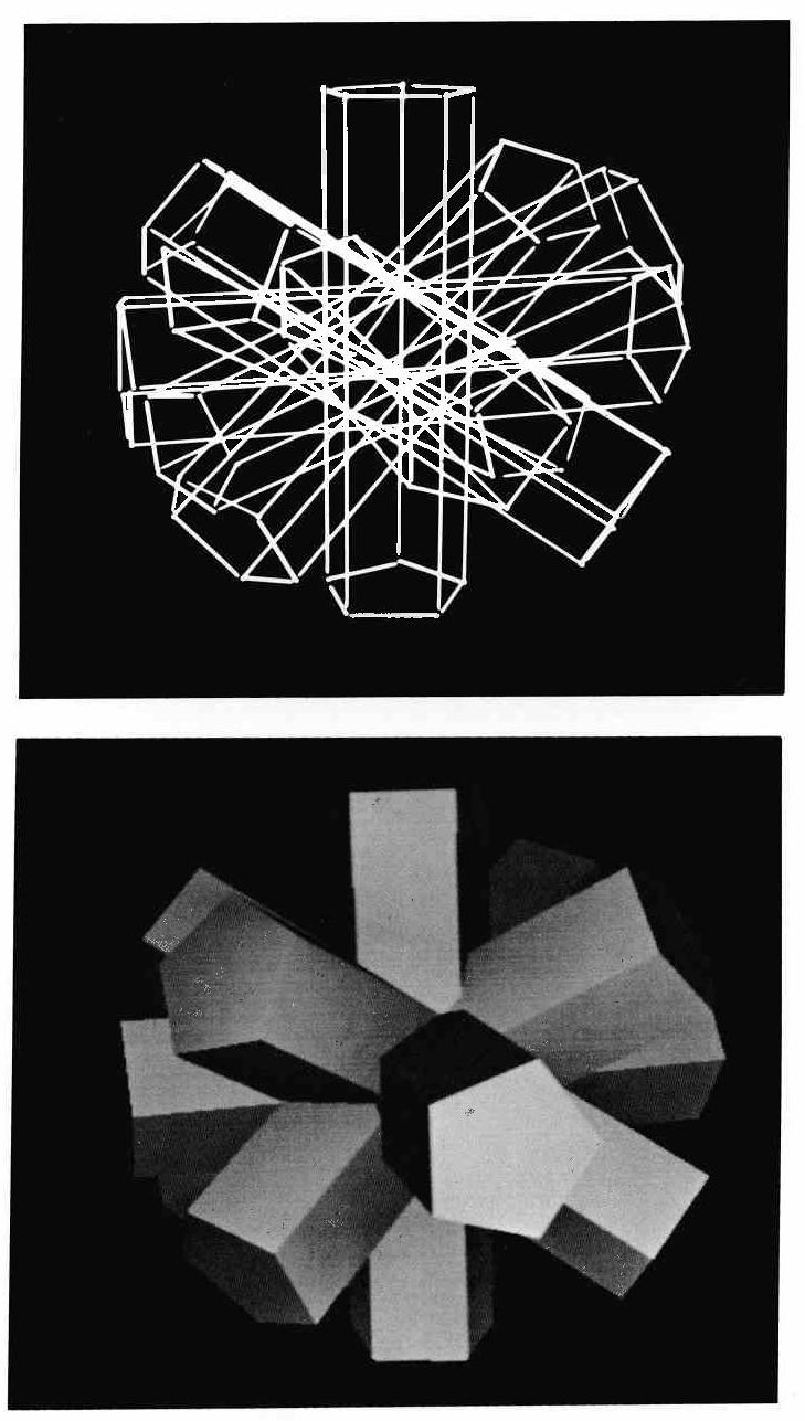
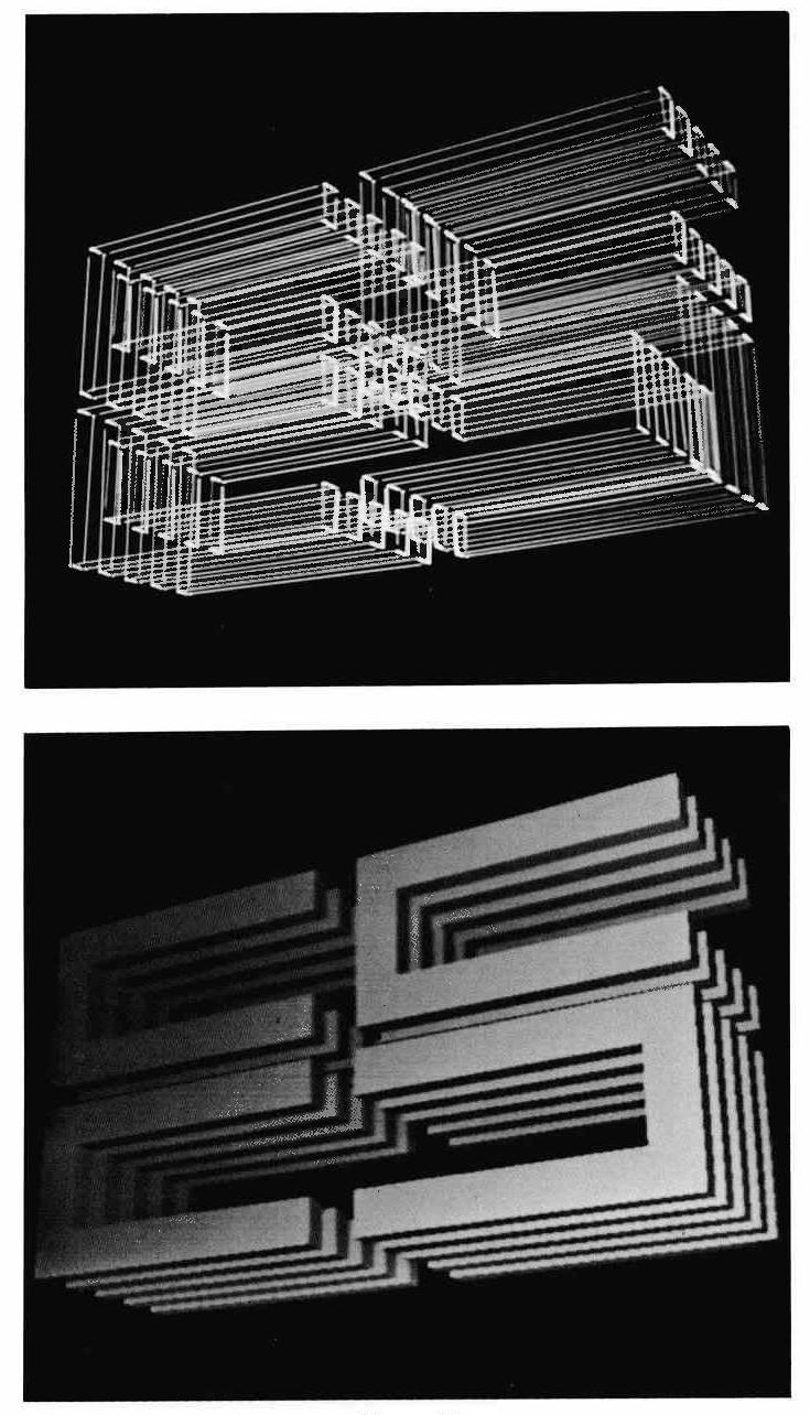
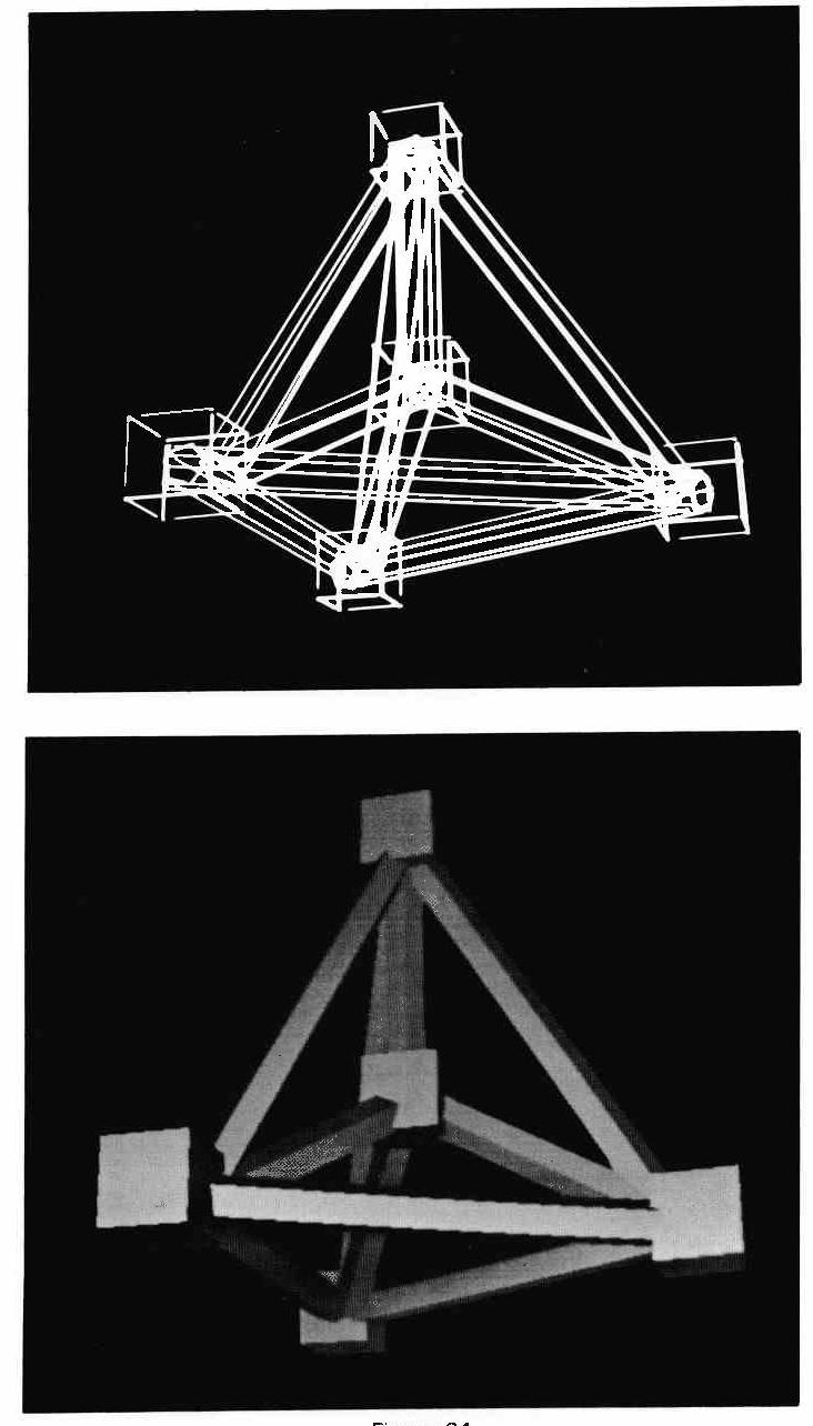
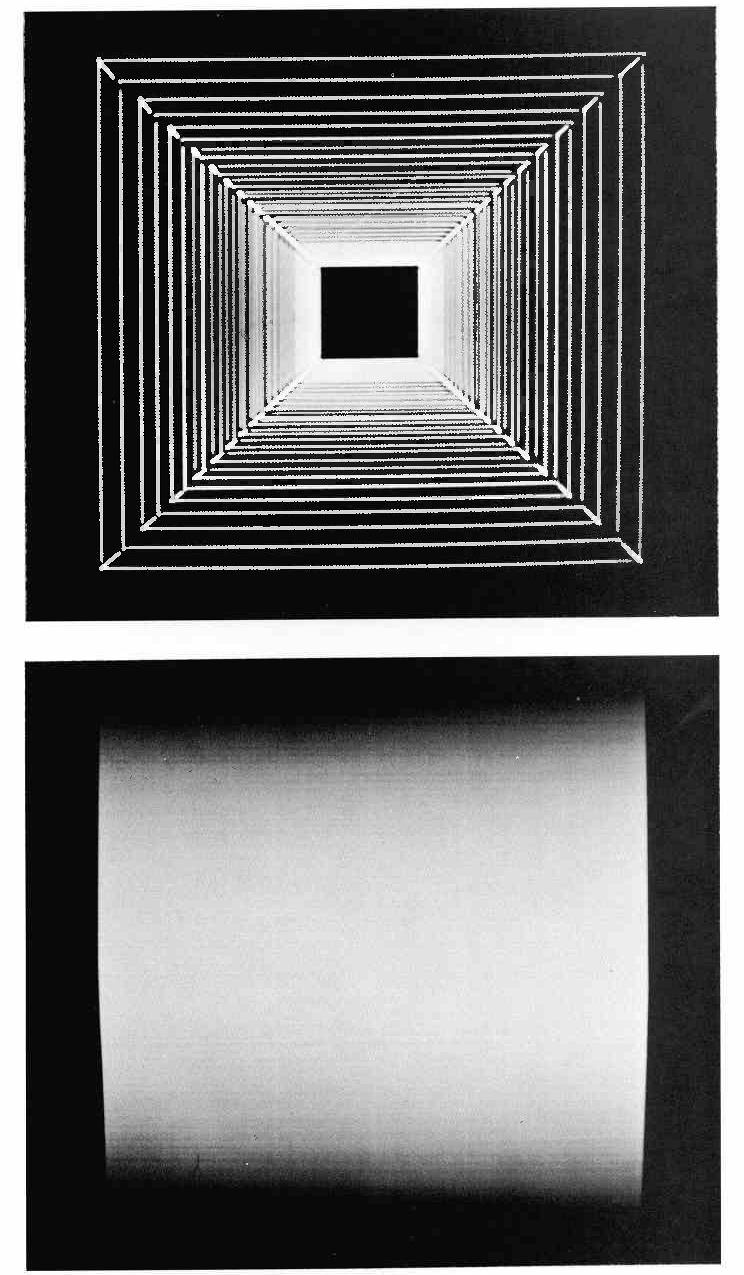
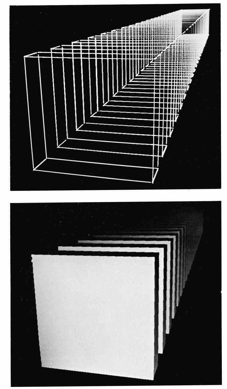
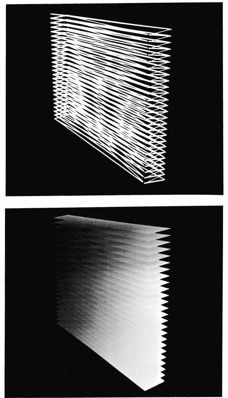
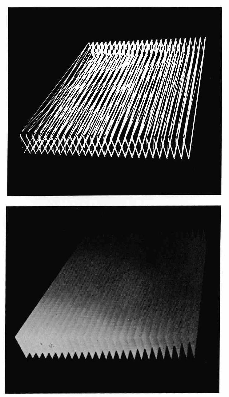
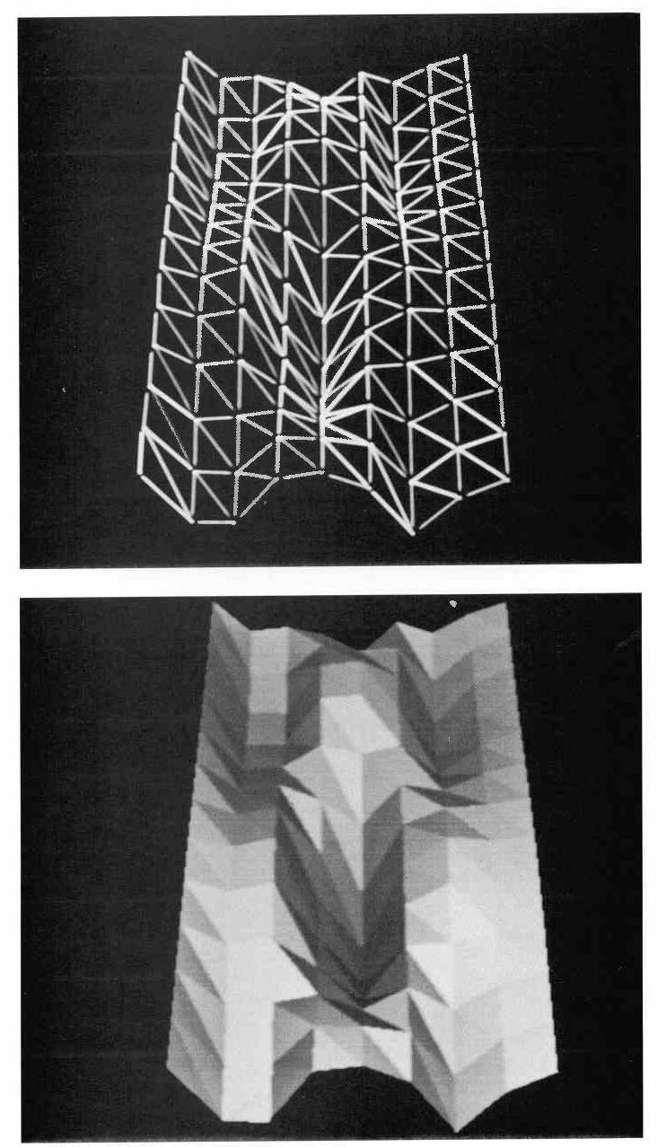
Ten objects were chosen to represent various complexities of pictures. Figures 22-31 contain pictures of the objects. Each object has two pictures. One shows all edges in the picture and the other shows the objects after visible surfaces are found and shaded.
Object 1, Penetration: The object is relatively simple but has many intersecting planes.
Object 2, E-S: Many edges abound in the picture and a great amount of visible complexity exists.
Object 3, Low Area: Although intersections abound, the picture only occupies a small area.
Object 4,Cube1: Twenty-five cubes exist, but only the front cube is visible.
Object 5, Cube2: Object 4 has been rotated so that parts of all twenty-five cubes are visible. An enormous amount of visible complexity exists.
Object 6, Shape1: This object is made up of many long and narrow polygons which are long in the X direction.
Object 7, Shape2: Object 6 has been rotated so the polygons are long in the Y direction. These two objects are to show what effect the object orientation can have on the scanning process.
Object 8, Sheet: This is a wavy object made up of triangles. Everything is at least partly visible.
Object 9, Simple1: This object is made up of a large cube encompassing a sphere and intersecting cubes.
Object 10, Simple2: Object 9 has been changed slightly so the sphere intersects the cube and is partly visible.
For each of the VSG algorithms mentioned in Chapter VI, statistics were gathered. These statistics included data about the object (number of polygons, etc.), computation required, memory reference counters, and various other counters. Appendix II contains a list of statistics. At the beginning of each set of statistics for a particular algorithm, there is a table describing the various counters. Figure 32 contains a table of statistics that have been extracted for the Penetration object (Figure 22). The statistics of the six various changes in the algorithm are shown for that object. The table in Figure 33 shows a cross section of statistics for all the objects with the final algorithm.
| VSG1 | VSG2 | VSG3 | VSG4 | VSG5 | VSG6 | |
|---|---|---|---|---|---|---|
| 1 | 137607 | 101892 | 37919 | 21730 | 21224 | 24291 |
| 2 | 9172 | 112 | 38 | 54 | 54 | 56 |
| 3 | 76 | 44 | 25 | 24 | 23 | 23 |
| 4 | 7068 | 6975 | 6839 | 9210 | - | - |
| 5 | 26 | 22 | 22 | 15 | - | - |
| 6 | - | - | - | - | 35604 | 32925 |
1  Number of memory references required
2  Number of total memory blocks used
3  Maximum number of blocks used at a time
4  Number of multiplications for depth test
   required (If multiplier-divider used)
5  Number of divisions for intersections
   required (If multiplier-divider used)
6  Number of addition cycles required for
   depth comparisons (If multiplier-divider used)
| PENETRATION | E-S | LOW AREA | CUBE1 | CUBE2 | SHAPE1 | SHAPE2 | SHEET | SIMPLE1 | SIMPLE2 | |
|---|---|---|---|---|---|---|---|---|---|---|
| 1 | 49 | 200 | 100 | 150 | 150 | 100 | 100 | 192 | 148 | 148 |
| 2 | 105 | 480 | 210 | 300 | 300 | 201 | 201 | 308 | 308 | 308 |
| 3 | 8802 | 15278 | 9154 | 7158 | 15410 | 12424 | 25590 | 12500 | 6172 | 6664 |
| 4 | 14 | 0 | 31 | 0 | 0 | 0 | 0 | 0 | 0 | 21 |
| 5 | 3844 | 7052 | 4193 | 1238 | 8221 | 5630 | 12023 | 6935 | 1652 | 2383 |
| 6 | 56 | 246 | 109 | 25 | 121 | 50 | 75 | 250 | 66 | 90 |
| 7 | 23 | 40 | 31 | 25 | 46 | 24 | 50 | 31 | 18 | 22 |
| 8 | 24291 | 47030 | 24071 | 7608 | 80945 | 34314 | 79762 | 26970 | 9039 | 14926 |
| 9 | 2.75 | 3.07 | 2.62 | 1.06 | 5.25 | 2.76 | 3.11 | 2.15 | 1.46 | 2.23 |
| 10 | 32925 | 47174 | 25641 | 10374 | 109190 | 30227 | 85941 | 14176 | 12326 | 24983 |
| 11 | 3.38 | 2.59 | 3.23 | 2.89 | 2.05 | 2.12 | 2.66 | 2.07 | 3.74 | 4.94 |
| 12 | 2.96% | 3.48% | 4.06% | 0.00% | 4.26% | 1.69% | 0.52% | 1.17% | 1.12% | 1.07% |
| 13 | 10 | 30 | 10 | 3 | 1700 | 10 | 1600 | 25 | 5 | 7 |
Before any statistics were gathered, arithmetic computation was suspected to be the bottle-neck in solving the hidden line problem. Statistics, however, showed that memory bandwidth was the critical factor, with the polygon segment block being the most accessed array! For the hardware processor, a special purpose memory would be used where 300 bits could be accessed at one time. With semiconductor memories it is becoming economical to do this.
From the first five different changes in the algorithm in Figure 32, one can see a steady decrease in the number of memory references. The final algorithm, however, produced an increase in memory references due to the X-sort technique described in Chapter III-F. In spite of this apparent increase in memory references for VSG6, the overall number of memory references in VSG5 would have been greater if accesses to the bucket X-sort memory had been counted. The design and cost for such a bucket X-sort memory also were compelling factors in deleting it even though accesses to the segment memory increased.
When the program proceeds from one scan line to the next, each segment block needs to be accessed for incrementing the X and Z values. At this same time, another X-sort list is being sorted in preparation for the following scan line. Segments are read from the beginning of the X-sort list for the current scan line and are usually inserted at the end of the X-sort list which is being prepared for the next scan line. Figure 33 (line 12) shows the percentage of times that segments cannot be inserted at the end of the list, and when the previous segment pointers must be used for finding the correct position in the list for inserting the segment block. The percentage varies between 0 to 4 percent for the ten test objects. Thus, the overhead of tracing back through a list to keep it sorted is extremely low. Also, no large, expensive, or possibly time-consuming special sorting hardware needs to be used.
Visual complexity is much more important in determining the speed of the algorithm than is the total object description. Object 4 and Object 5 are both sets of twenty-five cubes. However, Object 5 requires over ten times the number of memory references as Object 4. A picture visually identical to Object 4, but containing only one cube, was compared with Object 4. Even though Object 4 contained twenty-five cubes, it only had six times the memory references as the single cube object.
One way of measuring the performance of the algorithm is to create One way of measuring the performance of the algorithm is to create a relationship between the object description and the number of memory references (a read from memory followed by a write to memory) are always required to increment the X and Z values of a segment when proceeding from one scan line to the next scan line. From the total number of times edges cross scan lines (Line 3 of Figure 33), the minimum number of memory references needed can be calculated from equation 5.
Mmin = (S*N)/E (5)
where Mmin is the minimum number of memory references that can be expected. S is the number of memory references required to increment a segment (2). N is the total number of times that edges cross scan lines. E is the number of edges contained in a segment (2). Equation 5 reduces to Equation 6.
Mmin = N (6)
Equation 7 is the ratio (R) of Mtotal (the total number of memory references actually used) to Mmin.
R=Mtotal/Mmin (7)
Line 9 of Figure 33 lists the different values of R for the ten test objects.
The clipping of segments for depth sorting is very fast. Line 11 of Figure 33 contains the average number of add cycles required by the clipping registers to satisfy the depth comparison test between two polygon segments (see Chapter III-G). One of the add cycles is for loading the clipping registers. Even counting this, the average number is between two to three add cycles per depth test!
The ten test objects were also used by Stephen Mccallister [9] for gathering statistics on different versions of Warnock's algorithm. Comparisons are shown for a particular version which divides an area into four sub-areas using a vertex closest to the center of the large area for the common corner of the four sub-areas. If an area is completely covered by a polygon, is void of all polygons, or has only one visible edge in the area, it is simple enough to be displayed without further reduction.
Statistics for Object 2, E-S (Figure 23), were gathered. A large data structure was used requiring polygon lists, edge lists, and a vertex and planar equation array. Each polygon block consisted of several words. but only accesses to each polygon block (not word) were counted. The same was also true of the remaining data structure. The following information was gathered:
Polygon Block Accesses-----336,156
Edge Block Accesses--------427,688
Vertex Array---------------220,910
Planar Equation Array-------21,072
Total Accesses-----------1,005,826
The number of accesses to memory was far greater than that required by the new scan line algorithm (47,030). Also, Warnock's algorithm requires that the complete object description be stored in fast memory, and not just those objects pertaining to the current scan line.
Whenever a cathode ray tube (CRT) is being continually refreshed, the rate of moving the beam must remain constant if the displayed intensity is to be a function of the analog input intensity. That is, the X and Y deflection circuits must be changed at a constant rate. The output of the VSG does not generate segments at a rate inversely proportional to the length of the segments. Therefore, a buffer for temporarily storing segments must be inserted between the VSG and the display.
In Figure 26 (Object 5: Cube2), the Y scan goes from the bottom to the top of the picture. The VSG can quickly determine the visibility of the bottom half of the picture but will require a great amount of time for the top half of the picture. The display, however, must spend the same amount of time on each half of the picture. Because of this, almost the entire bottom half of the picture would need to be buffered. On the other hand in Figure 23 (Object 2: E-S), the VSG runs at a fairly constant rate over the whole picture, and only a small amount of buffering would be required.
For the ten test objects, line 13 of Figure 33 shows the smallest number of segments that must be stored at one time in order to have a display running at thirty frames per second with a constant rate for the X and Y deflection of the CRT beam. The VSG was simulated to reference the polygon segment array every 200 nanoseconds. For objects which have a uniform distribution over the area, only a small buffer size was needed. For Cube2, which has a concentration of visible information in the upper right hand corner, a much larger buffer size was required.
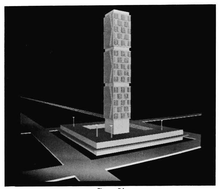
The processor described can be built with equipment available today. The segment memory must be in the 200 nanosecond cycle range, and semiconductor memories are available in this range. Also, only a small memory is required since 18 to 50 segment blocks at most are needed at any one time for any of the ten test objects.
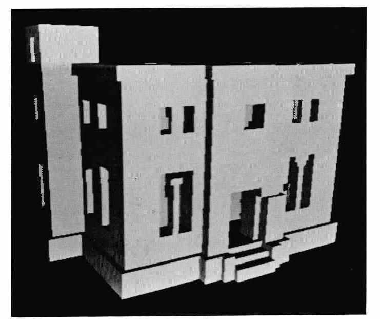
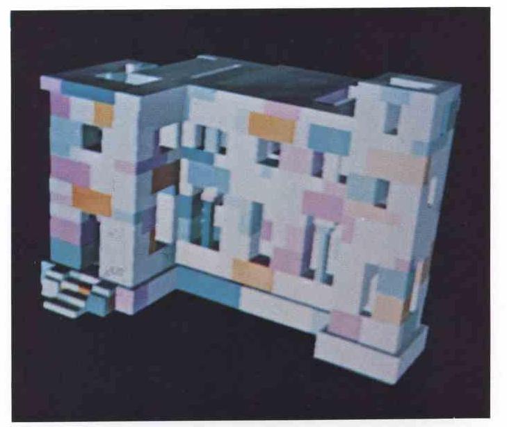
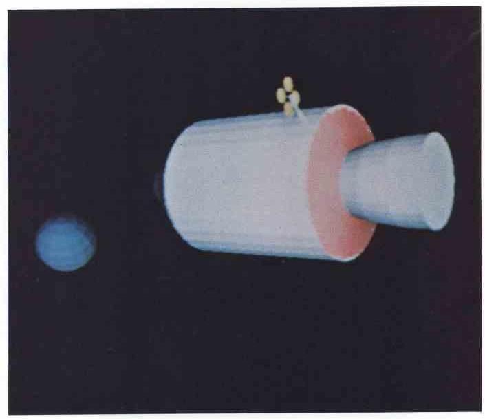
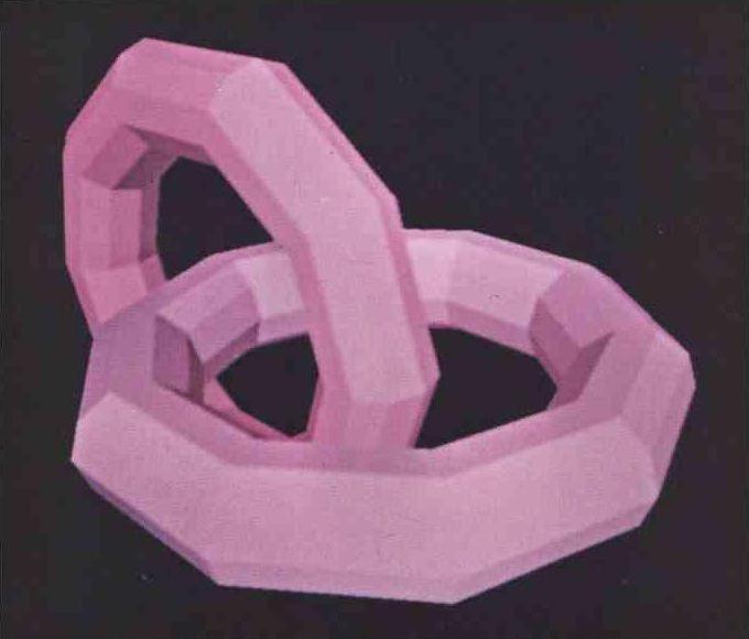
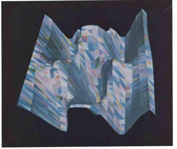
The algorithm has been simulated in Fortran IV on a PDP-10 at the Computer Science Department at the University of Utah. Other pictures have been taken to show how coloring and shading adds to the realism of objects. Figures 34-39 show various objects. Total computation time for generating and displaying the pictures is short. Cube1l (Object 4) required 30 seconds, and the church of Figure 35 containing 345 blocks (six polygons per block), required only 2.5 minutes. Figure 36 shows the back view of Figure 35 with the blocks randomly colored.
1. Roberts, L G, Machine Perception of Three Dimensional Solids, Technical Report No. 315, Lincoln Laboratory, 22 May 1963.
2. Loutrel, P P, A Solution to the Hidden-Line Problem for Computer-Drawn Polyhedra, IEEE Transactions on Computers, C-19 [3], 205 March 1970.
3. Appel, A, The Notion of Quantitative Invisibility and the Machine Rendering of Solids," ACM Conference Proc. 387 (1967).
4. Wylie, C, Romney, G, Evans, D C, Erdahl, A, Half-tone Perspective Drawings by Computer, FJCC67 , November 1967.
5. Romney, G, Computer Assisted Assembly and Rendering of Solids, Computer Science, University of Utah, Salt Lake City, Utah, August 1969.
6. Warnock, J, Generated Halftone Pictures," Technical Report 4-15, Computer Science, University of Utah, Salt Lake City, Utah, June 1969.
7. Bouknight, W J An Improved Procedure for Generation of Half-tone Computer Graphics Presentations, Report R-432, Coordinated Science Laboratory, University of Illinois, Urbana, Illinois, September 1969.
8. Sproull, R, Sutherland, I E, Clipping Divider, FJCC68, 765 (1968).
9. Mccallister, S, Sutherland, I E, Final Report on the Area Warnock Hidden Line Algorithm, Evans and Sutherland Computer Corporation, Salt Lake City, Utah, Internal Document, 12 February 1970.
The hidden line program is called as a subroutine from a main program. VSG6 contains counters interspersed throughout the program for gathering statistics like those in Appendix II. VSG6 is written in FORTRAN IV. Several subroutines are called by the program:
LDRPT (I,J) : loads the right half of J (sign extended) into I.
LDLPT(I,J) : loads the left half of J (sign extended) into I.
STRPT (I,J) : stores the right half of I into the right half of J. The left half of J remains undisturbed.
STLPT(I,J) : stores the right half of I into the left half of J. he right half of J remains undisturbed.SHOW : displays the segments stored in the VISSEG array.
LSTSET(N) : initializes a free list structure with blocks of N words each.
GETBLK(I) : gets a block from the free list. I is the index of that block and is set by the subroutine.
RETBLK(I) : returns a block to the free list. I is the index of the block to be returned.
A few minor changes have been made to the code to allow it to compile in a current FORTRAN compiler.
      SUBROUTINE HIDDEN(PIX,STAT)
      IMPLICIT INTEGER (A-Z)
      COMMON/FREE/EDGEST,DUM,POLYST
      COMMON/FREE1/Q1(4),FRAMEX ,FRAMEY
      COMMON/FREE2/X(1000),Y(1000),Z(1000),CX(700),CY(700),
     1CZ(700),CD(700)
      REAL X,Y,Z,CX,CY,CZ,CD
      LOGICAL DEPTH,ABLGE,ABRGE,ABRLE,ABLLE,ABBCKL,ABBCKR,
     1DELZ,CDBCKL,CDBCKR,JCLIP,J1BOX,JBOXES,J0BOX,
     2ADJNEW,ADJOLD,LOG,ZSADJ

      COMMON/SCOPE/VISSEG(512),BUCKY(512)
      DIMENSION EDGE(1),SEG(1),POLY(1)
      EQUIVALENCE (EDGEST,EDGE,SEG,POLY)
      DIMENSION ZS(10),SAM(3,2)
      DIMENSION PQ(16),Q(10,26),ADDS(20)
      PQL=16
      QL=26
C
C  PQ(1)=NUMBER OF TOTAL BLOCKS REQUIRED FOR
C        HIDDEN LINE WORK.
C  PQ(2)=MAXIMUM NUMBER OF TOTAL BLOCKS EVER USED AT ONE TIME.
c
C  PQ(3)=CURRENT NUMBER OF TOTAL BLOCKS AT A GIVEN TIME.
C        (USED FOR CALCULATING PQ(2).)
C  PQ(4)=TOTAL NUMBER OF EDGE BLOCKS IN FRAME.
C
C  PQ(5)=NUMBER OF EDGE BLOCKS WITH AT LEAST ONE OF THE
C        CONNECTED POLYGONS DRAWN CLOCKWISE.
C  PQ(6)=NUMBER OF THOSE EDGE BLOCKS OF PQ(5) WHOSE Y VALUE
C        OF THE BEGIN PT IS NOT THE SAME AS THE END PT Y VALUE.
C  PQ(7)=TOTAL NUMBER OF POLYGON BLOCKS IN THE FRAME.
C
C  PQ(8)=NUMBER OF POLYGON BLOCKS DRAWN CLOCKWISE.
C
C  PQ(9)=POINT DENSITY.
C
C  PQ(10)=NUMBER OF INVOLVED SCAN LINES.
C
C  PQ(11)=MEMORY REFERENCES FOR SEGMENT CREATOR.
C
C  PQ(12)=NANOSECONDS PER MEMORY REFERENCE FOR SEGMENT CREATOR.
C
C  PQ(13)=MEMORY REFERENCES FOR DEPTH CALCULATOR.
C
C  PQ(14)=NANOSECONDS PER MEMORY REFERENCE FOR DEPTH CALCULATOR.
C
C  PQ(15)=MEMORY REF, TOTAL PQI1,PQ13)
C
C  PQ(16)=NANOSECONDS FOR PQ(15).
C
C  ADDS(I)=NUMBER OF TIMES THE DEPTH TEST WAS SATISFIED IN.
C  Q COUNTERS
C  Q(1,X)=TOTAL PER FRAME
C  Q(2,X)=MAXIMUM REQUIRED OF A SCAN LINE
C  Q(3,X)=AVERAGE OF TOTAL SCAN LINES. ALSO SCRATCH FOR Q(2,X)
C  Q(4,X)=REQUIRED FOR PRE-FRAME PROCESSING
C  Q(5,X)=MAXIMUM REQUIRED FOR SCAN PREPARATION PROCESSING
C  Q(6,X)=NANOSECONDS REQUIRED. ALSO SCRATCH FOR Q(5,X)
C  Q(7,X)=MAXIMUM REQUIRED FOR SCAN DEPTH PROCESSING
C  Q(8,X)=AVERAGE OF ACTIVE SCAN LINES. ALSO SCRATCH FOR Q(7,X)
C  Q(9,X)=TOTAL FOR SCAN PREPARATION PROCESSING
C  Q(10,X)=TOTAL FOR SCAN DEPTH PROCESSING
C
C
C  Q(X,1)=NUMBER OF SLOPE CALCULATIONS.
C  Q(X,2>=NUMBER OF INTERCEPT CALCULATIONS.
C  Q(X,3)=NUMBER OF SAMPLE POINTS STORED FOR NEXT SCAN LINE.
C  Q(X,4)=SUBDIVISIONS (NOT FROM INTERSECTING CASE).
C  Q(X,5)=
C  Q(X,6)=DEPTH SAMPLES REQUIRED.
C  Q(X,7)=
C  Q(X,8)=SAMPLE POINTS DELETED.
C  Q(X,9)=
C  Q(X,10)=OUTPUT SEGMENTS.
C  Q(X,11)=INTERCEPT CALCULATIONS.
C  Q(X,12)=INTERCEPT SUBDIVISIONS.
C  Q(X,13)=OVERHEAD PIPELINE TIME.
C  Q(X,14)=TIME WAITING FOR CLIPPER.
C  Q(X,15)=READS FROM POLY.
C  Q(X,16)=WRITES TO POLY.
C  Q(X,17>=READS FROM EDGE.
C  Q(X,18)=WRITES TO EDGE.
C  Q(X,19)=READS FROM SEG
C  Q(X,20)=WRITES TO SEG
C  Q(X,21)=
C  Q(X,22)=
C  Q(X,23)=READS FROM FREE LIST(GETBLK)
C  Q(X,24)=WRITES TO FREE LIST(RETBLK)
C  Q(X,25)=READS FROM BUCKY
C  Q(X,26)=USED FOR SHADER
C      INITIALIZATION.
C
      DO 8 I=1,QL
      DO 8 J= 1,10
  8   Q(J,I)=0
      DO 9 I=1,PQL
  9   PQ(I)=0
      DO 12 I=1,20
 12   ADDS(I)=0
      DO 10 I=1,FRAMEY
 10   BUCKY(I)=0
      CALL LSTSET(14)
      DEPTH=.TRUE.
      SAM2S=0
      SAM2X=FRAMEX
      SEGS2=0
      SEGL2=0
      POLYCH=0
      IMPLST=0
C     GO THROUGH ALL POLYGONS AND NOTE WHICH WAY EACH POLYGON
C     IS DRAWN (CLOCKWISE OR COUNTER CLOCKWISE) BY CHECKING
C     CZ OF PLANAR EQUATIONS AND MARK THE POLYGON BLOCK.
      POLYPT=POLYST

 90   IF(POLYPT.EQ.0) GO TO 99
      POLY(POLYPT+1)=-1
      CALL LDRPT(INDEX,POLY(POLYPT+2))
      Q(1,15)=Q(1,15)+1
      PQ(7)=PQ(7)+1
      Q(1,16)=Q(1,16)+1
      IF(CZ(INDEX).LE.0) GO TO 95
      POLY(POLYPT+1)=0
      POLY(POLYPT+3)=0
      PQ(8)=PQ(8)+1
 95   CALL LDRPT(POLYPT,POLY(POLYPT))
      GO TO 90
C     INITIALIZATION CONTINUED.
C     TAKE EACH EDGE AND PUT IN THE BUCKY GIVEN BY ITS
C     SMALLEST Y VALUE. THIS IS THEY-SORT OF ENGES.
  99  EDGEPT=EDGEST
 100  IF(EDGEPT.EQ.0) GO TO 200
C
C     ENTER EACH EDGE IN BUCKY IF AT LEAST ONE OF THE
C     TWO POLYGONS IS DRAWN CLOCKWISE.
C
      CALL LDLPT(POLYL,EDGE(EDGEPT+2))
      CALL LDRPT(POLYR,EDGE(EDGEPT+2))
      Q(1,17)=Q(1,17)+1
      IF(POLYR.EQ.POLYL)GO TO 110
      IF(POLYL.EQ.0) GO TO 103
      IF(POLY(POLYL+1).EQ.0)GO TO 104
 103  IF(POLY(POLYR+1).LT.0)GO TO 110
      Q(1,15)=Q(1,15)+1
 104  CALL LDLPT(INDEX,EDGE(EDGEPT+1))
      YBEG=Y(INDEX)
      CALL LDRPT(INDEX,EDGE(EDGEPT+1))
      YEND=Y(INDEX)
      PQ(5)=PQ(5)+1
      IF(YBEG.EQ.YEND)GO TO 110
      PQ(6)=PQ(6)+1
      IF(YBEG.LT.YEND)GO TO 105
      I=YEND
      YEND=YBEG
      YBEG=I
 105  YBEG=YBEG+1
      IF(YBEG.LE.0)GO TO 115
      IF(YEND.GE.FRAMEY)GO TO 115
      I=BUCKY(YBEG)
      BUCKY(YBEG)=EDGEPT
      Q(1,18)=Q(1,18)+1
      CALL STLPT(I,EDGE(EDGEPT))
 110  CALL LDRPT(EDGEPT,EDGE(EDGEPT))
      GO TO 100
 115  CONTINUE
      PRINT 116
      RETURN
 116  FORMAT(' ERROR...OBJECT NOT IN BOUNDS OF FRAME1')
C     SCAN LINE COMPUTATION.
 200  CONTINUE
      DO 201 I=1,QL
 201  Q(4,I)=Q(1,I)
      IY=0
 204  IY=IY+1
      DO 202 I=1,QL
      Q(6,I)=Q(1,I)
      Q(9,1)=Q(9,1)-Q(1,I)
 202  Q(3,I)=Q(1,I)
C     INITIALIZE ALL POINTERS.
      SEGXST=SEGS2
      SEGLST=SEGL2
      SEGS2=0
      SEGL2=0
      SAM1S=SAM2S
      SAM1L=SAM2L
      SAM2S=0
      SAM1X=SAM2X
      SAM2X=FRAMEX
      IF(IY.GT.FRAMEY) GO TO 230
      SEGCNT=0
C     SCAN PREPARATION PROCESSING.
C     GET EDGES FROM BUCKY WHICH ENTER ON THIS SCAN LINE
C     AND BUILD THE SEGMENT LIST (SEG).
      IF(BUCKY(IY).EQ.0)GO TO 230
      Q(1,25)=Q(1,25)+1
      EDGEPT=BUCKY(IY)
 210  IF(EDGEPT.EQ.0)GO TO 230
      Q(1,17)=Q(1,17)+1
      CALL LDLPT(BEG,EDGE(EDGEPT+1))
      CALL LDRPT(END,EDGE(EDGEPT+1))
      YEND=Y(END)
      YBEG=Y(BEG)
      DELY=YBEG-YEND
      IF(DELY.EQ.0)GO TO 229
      IF(DELY.LT.0)GO TO 211
      I=BEG
      BEG=END
      END=I
      DELY=-DELY
 211  IX=X(BEG)*262144.0
      Q(1,1)=Q(1,1)+1
      XSLOPE=((X(END)-X(BEG))/(Y(END)-Y(BEG)))*262144.0
      DEL=(IY-YBEG)+262144.0
      IX=IX+ZMUL(XSLOPE,DEL)
      CALL LDLPT(IXE,IX)
      IF(IXE.LE.0.OR.IXE.GT.FRAMEX)GO TO 115
      II=-1
      CALL LDRPT(POLYPT,EDGE(EDGEPT+2))
C     TWO POLYGONS PER EDGE ARE ALLOWED.
 212  IF(POLYPT.EQ.0)GO TO 228
      Q(1,15)=Q(1,15)+1
      IF(POLY(POLYPT+1).EQ.-1) GO TO 228
      Q(1,16)=Q(1,16)+1
      IF(POLY(POLYPT+1).LT.0)GO TO 213
      POLY(POLYPT+1)=POLYCH
      POLYCH=POLYPT
      CALL STLPT(-1,POLY(POLYPT+1))
 213  SEGPT=POLY(POLYPT+3)
      PREV=0
      YEND2P=-1
 214  IF(SEGPT.EQ.0)GO TO 220
      Q(1,19)=Q(1,19)+1
      CALL LDRPT(YEND2,SEG(SEGPT+2))
      CALL LDLPT(YEND1,SEG(SEGPT+2))
      IF(YEND1.GE.0)GO TO 217
      TE1=IXSEG(SEGPT+3)-SEG(SEGPT+4)
      IF(TE1.EQ.0)TE1=XSLOPE-SEG(SEGPT+4)
      IF(TE1.LT.0)GO TO 220
      IF(YEND2.GE.0)GO TO 218
      TE2=IX-SEG(SEGPT+5)-SEG(SEGPT+6)
      IF(TE2.EQ.0)TE2=XSLOPE-SEG(SEGPT+6)
      IF(TE2.LT.0)GO TO 223
      GO TO 218
 217  IF(YEND2.GE.0) GO TO 218
      TE2=IX-SEG(SEGPT+5)-SEG(SEGPT+6)
      IF(TE2.EQ.0)TE2=XSLOPE-SEG(SEGPT+6)
      IF(TE2.GE.0)GO TO 218
      MODE=0
      PREV=SEGPT
      GO TO 227
 218  YEND2P=YEND2
      PREV=SEGPT
      CALL LDRPT(SEGPT,SEG(SEGPT+1))
      GO TO 214
 220  MODE=2
      IF(YEND2P.GE.0)GO TO 227
      FROM=0
      GO TO 226
 223  FROM=-1
      PREV=SEGPT
      CALL LDRPT(SEGPT,SEG(SEGPT+1))
      GO TO 226
 224  SEG(I+5)=SEG(PREV+5)
      SEG(I+6)=SEG(PREV+6)
      SEG(I+9)=SEG(PREV+9)
      SEG(I+10)=SEG(PREV+10)
      Q(1,20)=Q(1,20)+1
      CALL STRPT(YEND2,SEG(I+2))
      MODE=2
      GO TO 227
 226  CALL GETBLK(I)
      Q(3,23)=Q(1,23)+1
      PQ(1)=PQ(1)+1
      PQ(3)=PQ(3)+1
      IF(PQ(3).GT.PQ(2))PQ(2)=PQ(3)
      CALL STRPT(SEGPT,SEG(I+1))
      IF(PREV.NE.0)CALL STRPT(I,SEG(PREV+1))
      IF(PREV.NE.0)Q(1,20)=Q(1,20)+1
      IF(PREV.EQ.0)POLY(POLYPT+3)=I
      SEG(I)=-1
      SEG(I+2)=0
      SEG(I+11)=0
      CALL STLPT(POLYPT,SEG(I+1))
      IF(FROM.NE.0)GO TO 224
      PREV=I
 227  SEG(PREV+3+MODE)=IX-XSLOPE
      SEG(PREV+4+MODE)=XSLOPE
      Q(1,20)=Q(1,20)+1
      IF(MODE.EQ.0)CALL STLPT(DELY,SEG(PREV+2))
      IF(MODE.NE.0)CALL STPPT(DELY,SEG(PREV+2))
      SEG(PREV+8+MODE)=(Z(END)-Z(BEG))/(Y(END)-Y(BEG))+262144.0
      SEG(PREV+7+MODE)=Z(BEG)+262144.0
      SEG(PREV+7+MODE)=SEG(PREV+7+MODE)+ZMUL(SEG(PREV+8+MODE),DEL)
      SEG(PREV+7+MODE)=SEG(PREV+7+MODE)-SEG(PREV+8+MODE)
 228  CALL LDLPT(POLYPT,EDGE(EDGEPT+2))
      II=II+1
      IF(II.EQ.0)GO TO 212
 229  CALL LDLPT(EDGEPT,EDGE(EDGEPT))
      GO TO 210
C     SEGMENT PACKER AND SEGMENT ELIMINATOR.
 230  IF (POLYCH.EQ.0) GO TO 242
      Q(1,15)=Q(1,15)+1
      Q(1,16)=Q(1,16)+1
      CALL STLPT(0,POLY(POLYCH+I))
      NEXT=POLY(POLYCH+3)
      SEGPT=0
 231  IF (NEXT.EQ.0) GO TO 240
      PREV=SEGPT
      SEGPT=NEXT
      Q(1,19)=Q(1,19)+1
      CALL LDRPT(NEXT,SEG(SEGPT+1))
      IF (SEG(SEGPT+2).NE.0) GO TO 233
      IF(PREV.NE.0)Q(1,20)=Q(1,20)+1
      IF(PREV.NE.0)CALL STRPT(NEXT,SEG(PREV+1))
      IF(PREV.EQ.0)POLY(POLYCH+3)=NEXT
      Q(1,24)=Q(1,24)+1
      PQ(3)=PQ(3)-1
      CALL RETBLK(SEGPT)
      SEGPT=PREV
      GO TO 231
233   NEXTI=NEXT
      CALL LDRPT(YEND2,SEG(SEGPT+2))
      IF (YEND2.GE.0) GO TO 237
      CALL LDLPT(YEND1,SEG(SEGPT+2))
      IF (YEND1.LT.0)GO TO 2395
      SEG(SEGPT+3)=SEG(SEGPT+5)
      SEG(SEGPT+4)=SEG(SEGPT+6)
      SEG(SEGPT+7)=SEG(SEGPT+9)
      SEG(SEGPT+8)=SEG(SEGPT+10)
      CALL STLPT(YEND2,SEG(SEGPT+2))

237   IF(NEXT1.EQ.0)GO TO 241
      CALL LDLPT(YEND1,SEG(NEXT1+2))
      Q(1,19)=Q(1,19)+1
      IF (YEND1.GE.0) GO TO 238
      Q(1,20)=Q(1,20)+2
      CALL STRPT(YEND1,SEG(SEGPT+2))
      CALL STLPT(0,SEG(NEXT1+2))
      SEG(SEGPT+5)=SEG(NEXT1+3)
      SEG(SEGPT+6)=SEG(NEXT1+4)
      SEG(SEGPT+9)=SEG(NEXT1+7)
      SEG(SEGPT+10)=SEG(NEXT1+8)
      CALL LDLPT(S1,SEG(NEXTI))
      CALL LDRPT(S2,SEG(NEXT1))
      IF(S1.NE.0)CALL STRPT(S2,SEG(S1))
      IF(NEXT1.NE.SEGLST)CALL STLPT(S1,SEG(S2))
      IF(NEXT1.EQ.SEGLST)SEGLST=S1
      Q(1,20)=Q(1,20)+1
      SEG(NEXT1)=-1
      GO TO 2395
 238  CALL LDRPT(YEND2,SEG(NEXT1+2))
      IF(YEND2.GE.0) GO TO 239
      Q(1,20)=Q(1,20)+2
      CALL STRPT(YEND2,SEG(SEGPT+2))
      SEG(NEXT1+2)=0
      SEG(SEGPT+5)=SEG(NEXT1+5)
      SEG(SEGPT+6)=SEG(NEXT1+6)
      SEG(SEGPT+9)=SEG(NEXT1+9)
      SEG(SEGPT+10)=SEG(NEXT1+10)
      GO TO 2395
 239  CALL LDRPT(NEXT1,SEG(NEXT1+1))
      GO TO 237
 2395 IF(SEG(SEGPT).NE.-1)GO TO 231
      CALL LDLPT(IXE,SEG(SEGPT+3)+SEG(SEGPT+4))
      S1=PREV
 2396 IF(S1.NE.0)CALL LDBPT(S2,SEG(S1))
      IF(S1.EQ.0)S2=SEGXST
      IF (S1.EQ.SEGLST)S2=0
      Q(1,19)=Q(1,19)+1
      IF(S2.EQ.0)GO TO 2397
      CALL LDLPT(IX,SEG(S2+3)+SEG(S2+4))
      IF(IX.GE.IXE)GO TO 2397
      S1=S2
      GO TO 2396
 2397 IF(S2.NE.0)SEG(SEGPT)=S2
      Q(1,20)=Q(1,20)+1
      CALL STLPT(S1,SEG(SEGPT))
      IF(S1.NE.0)CALL STRPT(SEGPT,SEG(S1))
      IF(S1.EQ.0)SEGXST=SEGPT
      IF(S2.NE. 0)CALL STLPT(SEGT,SEG(S2))
      IF(S2.EQ.0)SEGLST=SEGPT
      GO TO 231
 240  POLYCH=POLY(POLYCH+1)
      GO TO 230
 241  PAUSE 'UNCLOSEn POLYGON'
      SEG(SEGPT+5)=SEG(SEGPT+3)
      SEG(SEGPT+6)=SEG(SEGPT+6)
      CALL STRPT(0,SEG(SEGPT+2))
      GO TO 2395
C     DEPTH SORTER.
 242  CONTINUE
      DO 276 I=1,QL
      Q(6,I)=Q(1,I)-Q(6,I)
      IF(Q(5,I).LT.Q(6,I))Q(5,I)=Q(6,I)
      Q(9,I)=Q(9,I)+Q(1,I)
      Q(10,I)=Q(10,I)-Q(1,I)
 276  Q(8,I)=Q(1,I)
      IF(IY.GT.FRAMEY) GO TO 498
      SAM(1,2)=1
      SAM(2,2)=0
      CALL LDLPT(SEGPT,IMPLST)
 278  IF(SEGPT.EQ.0)GO TO 279
      NEXT=SEG(SEGPT)
      CALL RETBLK(SEGPT)
      PQ(3)=PQ(3)-1
      Q(1,24)=Q(1,24)+1
      SEGPT=NEXT
      GO TO 278
 279  IMPLST=IMPLST*262144
      SEGACT=0
C            SAMPLE SPAN GENERATOR.
 281   SAM(1,1)=SAM(1,2)+1
       SAM(2,1)=SAM(2,2)
       SAM(3,1)=SAM(3,2)
       SAM(2,2)=0
       IF(SAM1X.GE.SAM(1,1))GO TO 282
       SAM1X=FRAMEX
       IF(SAM1S.EQ.SAM1L)GO TO 282
       CALL LDLPT(SAM1X,SEG(SAM1S))
       CALL LDRPT(SAM1S,SEG(SAM1S))
 282   SAM(1,2)=SAM1X
 299   ZS(1)=0
       FROM=0
       SEGPT=SEGACT
       SEGOUT=0
       PREV=0
C     CHECK SEGMENTS FROM THE CURRENT ACTIVE LIST.
 301  IF(SEGPT.EQ.0) GO TO 304
      NUMREF=-Q(1,19)-Q(1,20)-Q(1,13)
      Q(1,19)=Q(1,19)+1
      NEXT=SEG(SEGPT+11)
      XLEFT=SEG(SEGPT+3)
      XRIGHT=SEG(SEGPT+5)
      ZLEFT=SEG(SEGPT+7)
      ZRIGHT=SEG(SEGPT+9)
      CALL LDLPT(IXE,XLEFT)
      CALL LDLPT(IXX,XRIGHT)
      IF(IXX.LE.SAM(1,2))GO TO 303
      PREV=SEGPT
      IF(IXE.GE.SAM(1,2))GO TO 335
      GO TO 315
 303  CONTINUE
      Q(1,20)=Q(1,20)+1
      IF(PREV.NE.0)SEG(PREV+11)=NEXT
      IF(PREV.EQ.0)SEGACT=NEXT
      IF(IXX.LT.SAM(1,1)) GO TO 335
      Q(1,20)=Q(1,20)+1
      SEG(SEGPT+11)=SEGOUT
      IF (SEGOUT.EQ.0) SEGLO=SEGPT
      SEGOUT=SEGPT
      GO TO 315
C  CHECK NEW SEGMENTS FROM THE X-SORT LIST ALSO
C  INCREMENT THE X,Y,Z VALUES AND INSERT THE SEGMENT BLOCK
C  IN THE X-SORT LIST FOR THE NEXT SCAN LINE.
 304  SEGPT=SEGXST
      IF(SEGPT.EQ.0)GO TO 350
      NUMREF=-Q(1,19)-Q(1,20)-Q(1,13)
      Q(1,19)=Q(1,19)+1
      CALL LDLPT(IXE,SEG(SEGPT+3)+SEG(SEGPT+4))
      IF(IXE.GE.SAM(1,2))GO TO 350
      FROM=-1
      CALL LDRPT(SEGXST,SEG(SEGPT))
      IF(SEGPT.EQ.SEGLST)SEGXST=0
      Q(1,2)=Q(1,2)+1
      SEG(SEGPT+3)=SEG(SEGPT+3)+SEG(SEGPT+4)
      SEG(SEGPT+5)=SEG(SEGPT+5)+SEG(SEGPT+6)
      SEG(SEGPT+7)=SEG(SEGPT+7)+SEG(SEGPT+8)
      SEG(SEGPT+9)=SEG(SEGPT+9)+SEG(SEGPT+10)
      XLEFT=SEG(SEGPT+3)
      XRIGHT=SEG(SEGPT+5)
      ZLEFT=SEG(SEGPT+7)
      ZRIGHT=SEG(SEGPT+9)
      CALL LDLPT(YEND1,SEG(SEGPT+2))
      CALL LDRPT(YEND2,SEG(SEGPT+2))
      YEND1=YEND1+1
      YEND2=YEND2+1
      CALL STLPT(YEND1,SEG(SEGPT+2))
      CALL STRPT(YEND2,SEG(SEGPT+2))
      IF (SEG(SEGPT+11).GE.0) GO TO 309
      IF(YEND2.GE.0) GO TO 308
      IF (IXE+1.NE.SAM(1,1)) GO TO 308
      CALL LDLPT(IX,SEG(SEGPT+3)+SEG(SEGPT+4))
      IF(IX.LE.0.OR.IX.GT.FRAMEX) GO TO 308
      SAM(3,1)=SEGPT+12
      SAM(2,1)=IX
      FM=-1
      GO TO 3091
 308  CALL RETBLK(SEGPT)
      PQ(3)=PQ(3)-1
      Q(1,24)=Q(1,24)+1
      GO TO 335
 309  MODE=0
      SEG(SEGPT)=-1
      IF(YEND1.GE.0) GO TO 310
      MODE=-1
      CALL LDLPT(IX,SEG(SEGPT+3)+SEG(SEGPT+4))
      IF (IX.LE.0.OR.IX.GT.FRAMEX) GO TO 115
      FM=0

 3091 S2=0
      S1=SEGL2
 3092 IF(S1.EQ.0)GO TO 3094
      CALL LDLPT(IX1,SEG(S1+3)+SEG(S1+4))
      IF(IX.GE.IX1)GO TO 3094
      S2=S1
      CALL LDLPT(S1,SEG(S1))
      Q(1,19)=Q(1,19)+1
      GO TO 3092
 3094 IF(S2.NE.0)SEG(SEGPT)=S2
      Q(1,20)=Q(1,20)+1
      CALL STLPT(S1,SEG(SEGPT))
      IF(S2.NE.0)CALL STLPT(SEGPT,SEG(S2))
      IF (S2.EQ.0)SEGL2=SEGPT
      IF(S1.NE.0)CALL STRPT(SEGPT,SEG(S1))
      IF(S1.EQ.0)SEGS2=SEGPT
      IF(S2.NE.0)Q(1,20)=Q(1,20)+1
      IF(FM)335,310,364
 310  MODE=-MODE
      IF(YEND2.GE.0) GO TO 311
      MODE=-MODE
      CALL LDLPT(IX,SEG(SEGPT+5)+SEG(SEGPT+6))
      IF(IX.LE.0.OR.IX.GT.FRAMEX) GO TO 115
 311  IF(MODE.LT.0) GO TO 312
C     IF EITHER OF THE EDGES Or THE SEGMENT EXIT ON THIS
C     SCAN LINE (MODE), PUT THE CORRESPONDING POLYGON IN
C     THE POLYGON CHANGING LIST.
      CALL LDLPT(POLYPT,SEG(SEGPT+1))
      Q(1,15)=Q(1,15)+1
      IF(POLY(POLYPT+1).LT.0) GO TO 312
      Q(1,16)=Q(1,16)+1
      POLY(POLYPT+1)=POLYCH
      POLYCH=POLYPT
      CALL STLPT(-1,POLY(POLYPT+1))
 312  CALL LDLPT(IXX,XRIGHT)
      IF(IXE.GE.IXX) GO TO 335
      IF(IXX.GT.SAM(1,2)) GO TO 314
      SEG(SEGPT+11)=SEGOUT
      IF(SEGOUT.EQ.0) SEGLO=SEGPT
      SEGOUT=SEGPT
      GO TO 315
 314  SEG(SEGPT+11)=SEGACT
      SEGACT=SEGPT
 315  CONTINUE
      Q(1,6)=Q(1,6)+1
      IXLEFT=IXE
      IF(IXE.LT.SAM(1,1))IXLEFT=IXX
      CALL LDLPT(YEND1,SEG(SEGPT+2))
      IF(YEND1.GE.0)GO TO 316
      IF(IXE+1.NE.SAM(1,1))GO TO 316
      SAM(3,1)=SEGPT+12
      CALL LDLPT(SAM(2,1),SEG(SEGPT+3)+SEG(SEGPT+4))
 316  CALL LDRPT(YEND2,SEG(SEGPT+2))
      IF(YEND2.GE.0)GO TO 317
      IF(IXX.NE.SAM(1,2))GO TO 317
      SAM(3,2)=SEGPT+13
      CALL LDLPT(SAM(2,2),SEG(SEGPT+5)+SEG(SEGPT+6))
C     SIMULATION OF LOADING ANO RUNNING THE CLIPPER ARITHMETIC
C     UNIT FOR DEPTH COMPARISONS.
C     ADDITION TIME ONE.
 317  IF(XLEFT.NE.262143)XLTEST=XLEFT
      IF(XRIGHT.NE.262143)XRTEST=XRIGHT
      IF(FROM.NE.0)NUMADD=NUMADD+1
      DELNEW=(XRTEST-XLTEST)/262144
      IF(.NOT.DEPTH)DELNEW=DELNEW*1024
      IF((XLTEST-SAM(1,1)*262144).LT.0)XLTEST=SAM(1,1)*262144
      IF((XRTEST-SAM(1,2)*262144).GE.0)XRTEST=SAM(1,2)+262144
      ADJNEW=.FALSE.
      IF(ZLEFT.LT.ZRIGHT)ADJNEW=.TRUE.
      IF(ZS(1).EQ.0)GO TO 331
      ABLLE=.FALSE.
      ABLGE=.FALSE.
      ABRLE=.FALSE.
      ABRGE=.FALSE.
      IF(XLTEST.LE.ZS(6))ABLLE=.TRUE.
      IF(XLTEST.GE.ZS(6))ABLGE=.TRUE.
      IF(XRTEST.LE.ZS(7))ABRLE=.TRUE.
      IF(XRTEST.GE.ZS(7))ABRGE=.TRUE.
      IF(((.NOT.ABLGE).AND.(.NOT.ABRGE)).OR.((.NOT.ABLLE.AND.
     1(.NOT.ABRLE))))GO TO 329
      XLCLIP=XLTEST
      IF(ABLLE)XLCLIP=ZS(6)
      XRCLIP=XRTEST
      IF(ABRGE)XRCLIP=ZS(7)
      DEL=DELNEW
      IF(DELNEW.LT.ZSDEL)DEL=ZSDEL
      XAMXL=XLEFT-XLCLIP
      XBMXL=XRIGHT-XLCLIP
      XAMXR=XLEFT-XRCLIP
      XBMXR=XRIGHT-XRCLIP
      ZAL=ZLEFT
      ZBL=ZRIGHT
      ZAR=ZLEFT
      ZBR=ZRIGHT
      IF(ADJNEW)GO TO 320
      ZBL=ZLEFT
      ZAL=ZRIGHT
      ZBR=ZLEFT
      ZAR=ZRIGHT
 320  XCMXL=ZS(2)-XLCLIP
      XDMXL=ZS(3)-XLCLIP
      XCMXR=ZS(2)-XRCLIP
      XDMXR=ZS(3)-XRCLIP
      IF(ZS(1)-2.GE.0)GO TO 321
      ZCL=ZS(4)
      ZDL=ZS(5)
      ZCR=ZS(4)
      ZDR=ZS(5)
      ADJOLD=ZSADJ
      GO TO 323
 321  ADJOLD=.NOT.ADJNEW
      IF(ADJNEW)GO TO 322
      ZCL=ZS(4)
      ZDL=ZS(4)
      ZCR=ZS(5)
      ZDR=ZS(5)
 322  ZCL=ZS(5)
      ZDL=ZS(5)
      ZCR=ZS(4)
      ZDR=ZS(4)

C  CLIP STATE*** ONE ADD TIME EACH PASS.
 323  ABBCKL=.FALSE.
      ABBCKR=.FALSE.
      CDBCKL=.FALSE.
      CDBCKR=.FALSE.
      DELZ=.FALSE.
      NUMADD=NUMADD+1
      XHOLDL=(XAMXL+XBMXL)/2
      ZHOLDL=(ZAL+ZBL)/2
      XHOLDR=(XAMXR+XBMXR)/2
      ZHOLDR=(ZAR+ZBR)/2
      XTEMPL=(XCMXL+XDMXL)/2
      ZTEMPL=(ZCL+ZDL)/2
      XTEMPR=(XCMXR+XDMXR)/2
      ZTEMPR=(ZCR+ZDR)/2
      DEL=DEL/2
      IF(ZAL-ZDL.GE.0)ABBCKL=.TRUE.
      IF(ZCL-ZBL.GE.0)CDBCKL=.TRUE.
      IF(ZAR-ZDR.GE.0)ABBCKR=.TRUE.
      IF(ZCR-ZBR.GE.0)CDBCKR=.TRUE.
      IF(DEL.EQ.0)DELZ=.TRUE.
c23456789012345678901234567890123456789012345678901234567890123456
      LOG=((.NOT.ABLGE.OR..NOT.ABRLE).AND.((CDBCKL.AND..NOT.ABBCKR
     1.AND..NOT.CDBCKR).OR.(.NOT.ABBCKL.AND..NOT.CDBCKL.AND.CDBCKR
     2).OR.(.NOT.ABBCKL.AND..NOT.CDBCKL.AND..NOT.ABBCKR)))
      LOG=LOG.OR.(.NOT.ABLLE.OR..NOT.ABRGE).AND.((ABBCKL.AND.
     1.NOT.ABBCKR.AND..NOT.CDBCKR).OR.(.NOT.ABBCKL.AND..NOT.CDBCKL
     2.AND.ABBCKR.OR.(.NOT.ABBCKL.AND..NOT.CDBCKL.AND..NOT.
     3CDBCKR)))
      LOG=LOG.OR.((.NOT.(ABBCKL.AND.ABBCKR).AND..NOT.(CDBCKL.AND.
     1CDBCKR)).AND.(ABLGE.AND.ABRLE.AND.ABLLE.AND.ABRGE))
      JCLIP=LOG.AND..NOT.DELZ
      LOG=((ABLGE.AND.ABRLE).AND.((ABBCKL.AND.ABBCKR).OR.(ABBCKL.AND.
     1.NOT.CDBCKR.AND.DELZ).OR.(ABBCKR.AND..NOT.CDBCKL.AND.DELZ)
     2.OR.(.NOT.CDBCKL.AND..NOT.CDBCKR.AND.DELZ)))
      J0BOX=LOG.OR.(DELZ.AND..NOT.ABBCKL.AND..NOT.CDBCKL
     1.AND..NOT.ABBCKR.AND..NOT.CDBCKR.AND.ABLGE.AND.ABRLE)
      LOG=(ABLLE.AND.ABRGE).AND..NOT.(ABLGE.AND.ABRLE.AND.((ABBCKL.
     1AND.ABBCKR).OR.(ABBCKL.AND.CDBCKR).OR.(ABBCKR
     2.AND..NOT.CDBCKL)))
      LOG=LOG.AND.((CDBCKL.AND.CDBCKR).OR.(CDBCKL.AND.
     1.NOT.ABBCKR.AND.DELZ).OR.(CDBCKR.AND..NOT.ABBCKL.AND.DELZ))
      J1BOX=LOG.OR.(DELZ.AND..NOT.ABBCKL.AND..NOT.CDBCKL
     1.AND..NOT.ABBCKR.AND..NOT.CDBCKR.AND.((ABLLE
     2.AND..NOT.ABRLE).OR.(.NOT.ABLGE.AND.ABRGE)))
      LOG=(DELZ.AND.((ABBCKL.AND..NOT.CDBCKL.AND..NOT.ABBCKR.AND.
     1CDBCKR).OR.(.NOT.ABBCKL.AND.CDBCKL.AND.ABBCKR
     2.AND..NOT.CDBCKR)))
      LOG=LOG.OR.((.NOT.ABLGE.OR..NOT.ABRLE).AND.((ABBCKL
     1.AND..NOT.CDBCKL).OR.(ABBCKR.AND..NOT.CDBCKR)))
      LOG=LOG.OR.((.NOT.ABLLE.OR..NOT.ABRGE).AND.((CDBCKL
     1.AND..NOT.ABBCKL).OR.(CDBCKR.AND..NOT.ABBCKR)))
      JBOXES=LOG.OR.(DELZ.AND..NOT.ABBCKL.AND..NOT.CDBCKL
     1.AND..NOT.ABBCKR.AND..NOT.CDBCKR.AND.((.NOT.ABLLE
     2.AND..NOT.ABRLE).OR.(.NOT.ABLGE.AND..NOT.ABRGE)))
      NUMCNT=0
      IF(JCLIP) NUMCNT=NUMCNT+1
      IF(J1BOX) NUMCNT=NUMCNT+1
      IF(JBOXES)NUMCNT=NUMCNT+1
      IF(J0BOX) NUMCNT=NUMCNT+1
      IF(NUMCNT.NE.1)PAUSE
      IF(JCLIP) GO TO 325
      IF(J1BOX) GO TO 331
      IF(JBOXES) GO TO 329
      IF(J0BOX)GO TO 335
  325 IF(XHOLDL.GE.0)XBXML=XHOLDL
      IF(XHOLDL.GE.0.AND.ADJNEW)ZBL=ZHOLDL
      IF(XHOLDL.GE.0.AND.(.NOT.ADJNEW))ZAL=ZHOLDL
      IF(XHOLDL.LT.0)XAMXL=XHOLDL
      IF(XHOLDL.LT.0.AND.ADJNEW)ZAL=ZHOLDL
      IF(XHOLDL.LT.0.AND.(.NOT.ADJNEW))ZBL=ZHOLDL
      IF(XHOLDR.GE.0)XBXMR=XHOLDR
      IF(XHOLDR.GE.0.AND.ADJNEW)ZBR=ZHOLDR
      IF(XHOLDR.GE.0.AND.(.NOT.ADJNEW))ZAR=ZHOLDR
      IF(XHOLDR.LT.0)XAMXR=XHOLDR
      IF(XHOLDR.LT.0.AND.ADJNEW)ZAR=ZHOLDR
      IF(XHOLDR.LT.0.AND.(.NOT.ADJNEW))ZAR=ZHOLDR
      IF(XTEMPL.GE.0)XDMXL=XTEMPL
      IF(XTEMPL.GE.0.AND.ADJOLD)ZDL=ZTEMPL
      IF(XTEMPL.GE.0.AND.(.NOT.ADJOLD))ZCR=ZTEMPR
      IF(XTEMPL.LT.0)XCMXL=XTEMPL
      IF(XTEMPL.LT.0.AND.ADJOLD)ZCL=ZTEMPL
      IF(XTEMPL.LT.0.AND.(.NOT.ADJOLD))ZCR=ZTEMPR
      IF(XTEMPR.GE.0)XDMXR=XTEMPR
      IF(XTEMPR.GE.0.AND.ADJOLD)ZDR=ZTEMPR
      IF(XTEMPR.GE.0.AND.(.NOT.ADJOLD))ZCR=ZTEMPR
      IF(XTEMPR.LT.0)XCMXR=XTEMPR
      IF(XTEMPR.LT.0.AND.ADJOLD)ZCR=ZTEMPR
      IF(XTEMPR.LT.0.AND.(.NOT.ADJOLD))ZDR=ZTEMPR
  326 DEL=ZSDEL
      XAMXL=XLCLIP
      XBMXL=XRCLIP
      ZAL=ZAL-ZCL
      ZBL=ZAR-ZCR
  327 ZHOLDL=(ZAL+ZBL)/2
      XHOLDL=(XAMXL+XBMXL)/2
      NUMADD=NUMADD+1
      DEL=DEL/2
      IF(DEL.EQ.0) GO TO 335
      IF(IEOR(ZAL,ZHOLDL).GE.0)XAMXL=XHOLDL
      IF(IEOR(ZBL,ZHOLDL).GE.0)XBMXL=XHOLDL
      IF(IEOR(ZAL,ZHOLDL).GE.0)ZAL=ZHOLDL
      IF(IEOR(ZBL,ZHOLDL).GE.0)ZBL=ZHOLDL
      GO TO 327

C     EXPAND BOX TO INCLUDE OLD BOX AND NEW LINE CLIPPED.
 329  ZS(1)=ZS(1)+1
      IF(.NOT.DEPTH)GO TO 326
      IF(ABRLE.AND.ABRGE.AND.ABLLE.AND.ABLGE)GO TO 3295
      IF(ZLEFT-ZS(4).LT.0.AND.ADJNEW)ZS(4)=ZLEFT
      IF(ZRIGHT-ZS(4).LT.0.AND.(.NOT.ADJNEW))ZS(4)=ZRIGHT
      IF(ZLEFT-ZS(5).GE.0.AND.(.NOT.ADJNEW))ZS(5)=ZLEFT
      IF(ZRIGHT-ZS(5).GE.0.AND.ADJNEW)ZS(5)=ZRIGHT
      GO TO 330

 3295 IF(ADJNEW.AND.ADJOLD.AND.CDBCKL)ZS(4)=ZAL
      IF(ADJNEW.AND.ADJOLD.AND.ABBCKL)ZS(4)=ZCL
      IF(ADJNEW.AND..NOT.ADJOLD.AND.ZAL.LT.ZCR)ZS(4)=ZAL
      IF(ADJNEW.AND..NOT.ADJOLD.AND.ZAL.GE.ZCR)ZS(4)=ZCR
      IF(.NOT.ADJNEW.AND.ADJOLD.AND.ZAR.LT.ZCL)ZS(4)=ZAR
      IF(.NOT.ADJNEW.AND.ADJOLD.AND.ZAR.GE.ZCL)ZS(4)=ZCL
      IF(.NOT.ADJNEW.AND..NOT.ADJOLD.AND.CDBCKR)ZS(4)=ZAR
      IF(.NOT.ADJNEW.AND..NOT.ADJOLD.AND.ABBCKR)ZS(4)=ZCR
      IF(ADJNEW.AND.ADJOLD.AND.CDBCKR)ZS(5)=ZDR
      IF(ADJNEW.AND.ADJOLD.AND.ABBCKR)ZS(5)=ZBR
      IF(ADJNEW.AND..NOT.ADJOLD.AND.ZBR.LT.ZDL)ZS(5)=ZDL
      IF(ADJNEW.AND..NOT.ADJOLD.AND.ZBR.GE.ZDL)ZS(5)=ZBR
      IF(.NOT.ADJNEW.AND.ADJOLD.AND.ZBL.LT.ZDR)ZS(5)=ZDR
      IF(.NOT.ADJNEW.AND.ADJOLD.AND.ZBL.GE.ZDR)ZS(5)=ZBL
      IF(.NOT.ADJNEW.AND..NOT.ADJOLD.AND.CDBCKL)ZS(5)=ZDL
      IF(.NOT.ADJNEW.AND..NOT.ADJOLD.AND.ABBCKL)ZS(5)=ZBL
 330  IF(ABLLE)ZS(6)=XLTEST
      IF(ABRGE)ZS(7)=XRTEST
      ZSDEL=0
      ZS(10)=SEGPT
      IF(ABBCKL)GO TO 335
      ZS(10)=ZS(9)
      ZS(9)=SEGPT
      GO TO 335
C     MAKE A ONE ELEMENT BOX.
 331  ZS(1)=I
      ZS(2)=XLEFT
      ZS(3)=XRIGHT
      IF(ADJNEW)ZS(4)=ZLEFT
      IF(.NOT.ADJNEW)ZS(4)=ZRIGHT
      IF(ADJNEW)ZS(5)=ZRIGHT
      IF(.NOT.ADJNEW)ZS(5)=ZLEFT
      ZS(6)=XLTEST
      ZS(7)=XRTEST
      ZS(8)=IXLEFT
      ZS(9)=SEGPT
      ZSADJ=ADJNEW
      ZSDEL=DELNEW
 335  CONTINUE
      NUMREF=(NUMADD+1)/2-Q(1,13)-Q(1,19)-Q(1,20)-NUMREF
      IF(NUMREF.GT.0)Q(1,14)=Q(1,14)+NUMREF
      IF(NUMADD.GT.20)NUMADD=20
      IF(NUMADD.LE.0)NUMADD=1
      ADDS(NUMADD)=ADDS(NUMADD)+1
      IF(.NOT.DEPTH)GO TO 402
      SEGPT=NEXT
      IF(FROM.EQ.0)GO TO 301
      GO TO 304
C     INTEREGATE THE ZS BOX
  350 CONTINUE
      Q(1,13)=Q(1,13)+1
      IF(ZS(1)-2.LT.0)GO TO 355
      IF(SAM(1,1)-SAM(1,2).EQ.0)PAUSE "SINGLE"
      IF(ZS(1).EQ.2.AND.(ZS(8).GE.SAM(1,2))) GO TO 400
C     SUBDIVISION NECESSARY.
      Q(1,4)=Q(1,4)+1
      IF(SEGOUT.EQ.0) GO TO 351
      SEG(SEGLO+11)=SEGACT
      SEGACT=SEGOUT
      Q(1,20)=Q(1,20)+1
      Q(1,19)=Q(1,19)+1
 351  IF(ZS(8)-SAM(1,2).LT.0)GO TO 353
C     SUBDIVIDE IN THE MIDDLE.
      Q(1,12)=Q(1,12)+1
      SAM(1,2)=(SAM(1,1)+SAM(1,2))/2
      GO TO 299
C     SUBDIVIDE AT IXLEFT.
  353 SAM(1,2)=ZS(8)
      GO TO 299


C OUTPUT SEGMENTS
  355 IF(ZS(1).GT.0)GO TO 358
      SAM(2,1)=0
      Q(1,8)=Q(1,8)+1
  356 XEND=SAM(1,2)
      POLYPT=0
      NEXTGO=1
      GO TO 368
  358 CALL LDLPT(XEND,ZS(6))
      IF(XEND.EQ.SAM(1,1)) GO TO 368
      POLYPT=0
      NEXTGO=2
      GO TO 368
  360 CALL LDLPT(XEND,ZS(7))
      POLYPT=ZS(9)
      CALL LDLPT(POLYPT,SEG(POLYPT+1))
      CALL LDLPT(XTEMP,ZS(6))
      PQ(9)=PQ(9)+XEND-XTEMP+1
      NEXTGO=3
      GO TO 368
  362 IF(XEND.EQ.SAM(1,2))GO TO 376
      GO TO 356
  364 POLYPT=ZS(9)
      CALL LDLPT(POLYPT,SEG(POLYPT+1))
      PQ(9)=PQ(9)+SAM(1,2)-SAM(1,1)+ 1
      NEXTGO=4
      GO TO 368
  365 XEND=SAM(1,2)
      POLYPT=ZS(10)
      CALL LDLPT(POLYPT,SEG(POLYPT+1))
      NEXTGO=1
      IF(FM.EQ.0)GO TO 368
      SAM(2,1)=IX
      SAM(3,1)=SEGPT+12
C     OUTPUT A SPECIFIC SEGMENT.
  368 IF(SEGCNT.EQ.0)GO TO 372
      IF(POLYPT.NE.PRESEG)GO TO 372
      SAM(2,1)=0
      Q(1,8)=Q(1,8)+1
      GO TO 374
 372  SEGCNT=SEGCNT+1
      Q(1,10)=Q(1,10)+1
      PRESEG=POLYPT
 374  VISSEG(SEGCNT)=XEND
      CALL STLPT(POLYPT,VISSEG(SEGCNT))
      IF(SAM(2,1).EQ.0)GO TO 3755
C  STORE A SAMPLE POINT.
      Q(1,3)=Q(1,3)+1
      IF(SAM2S.NE.0)GO TO 375
      SAM2S=SAM(3,1)
      SAM2X=SAM(2,1)
      SAM2LX=SAM(2,1)
      SAM2L=SAM(3,1)
      GO TO 3755
 375  IF(SAM(2,1).LE.SAM2LX)GO TO 3755
      SAM2LX=SAM(2,1)
      CALL STRPT(SAM(3,1),SEG(SAM2L))
      CALL STLPT(SAM(2,1),SEG(SAM2L))
      SAM2L=SAM(3,1)
3755  SAM(2,1)=0
      GO TO (376,360,362,365),NEXTGO
 376  IF(SAM(1,2).EQ.FRAMEX) GO TO 498
      GO TO 281
C    INTERSECTING PLANES CASE.
 400  DEPTH=.FALSE.
      FM=0
      ZS(1)=0
      Q(1,11)=Q(1,11)+1
      SEGPT=ZS(9)
      NEXT=-1
 401  XLEFT=SEG(SEGPT+3)
      XRIGHT=SEG(SEGPT+5)
      ZLEFT=SEG(SEGPT+7)
      ZRIGHT=SEG(SEGPT+9)
      NUMREF=-Q(1,13)-Q(1,19)-Q(1,20)
      Q(1,19)=Q(1,19)+1
      GO TO 317
 402  NEXT=NEXT+1
      SEGPT=ZS(10)
      IF(NEXT.EQ.0) GO TO 401
      DEPTH=.TRUE.
      XXTEST=XAMXL
      CALL LDLPT(XEND,XXTEST)
      Q(1,19)=Q(1,19)+2
      IF(IY.EQ.FRAMEY)GO TO 364
      SEGSAM=ZS(10)
      CALL STLPT(ZS(9),SEGSAM)
      CALL LDLPT(SEGPT,IMPLST)
      PREV=0
 4010 IF(SEGPT.EQ.0)GO TO 4030
      Q(1,19)=Q(1,19)+1
      NEXT=SEG(SEGPT)
      IF(SEGSAM.NE.SEG(SEGPT+1)) GO TO 4020
      IF(PREV.EQ.0)CALL STLPT(NEXT,IMPLST)
      IF(PREV.NE.0)SEG(PREV)=NEXT
      SEG(SEGPT+4)=XXTEST-SEG(SEGPT+3)
      SEG(SEGPT+3)=XXTEST
      CALL LDLPT(IX,SEG(SEGPT+3)+SEG(SEGPT+4))
      IF(IX.LE.0.OR.IX.GT.FRAMEX) GO TO 4040
      FM=1
      GO TO 3091
 4020 PREV=SEGPT
      SEGPT=NEXT
      GO TO 4010
 4030 IF(IY.EQ.FRAMEY-1)GO TO 364
      CALL GETBLK(SEGPT)
      Q(1,23)=Q(1,23)+1
      PQ(1)=PQ(1)+1
      PQ(3)=PQ(3)+1
      IF(PQ(3).GT.PQ(2))PQ(2)=PQ(3)
      SEG(SEGPT+1)=SEGSAM
      SEG(SEGPT+2)= IY-FRAMEY+1
      SEG(SEGPT+11)=-1
      SEG(SEGPT+3)=XXTEST
      CALL LDRPT(SEG(SEGPT),IMPLST)
      CALL STRPT(SEGPT,IMPLST)
      GO TO 364
 4040 CALL RETBLK(SEGPT)
      PQ(3)=PQ(3)-1
      Q(1,24)=Q(1,24)+1
      GO TO 364
 498  CONTINUE
      DO 499 I=1,QL
      Q(10,I)=Q(10,I)+Q(1,I)
      Q(3,I)=Q(1,I)-Q(3,1)
      IF(Q(2,I).LT.Q(3,I))Q(2,I)=Q(3,I)
      Q(8,I)=Q(1,I)-Q(8,I)
 499  IF(Q(7,I).LT.Q(8,I))Q(7,I)=Q(8,I)
      IF(IY.GT.FRAMEY)GO TO 500
      IF(PIX.NE.0)CALL SHOW
      IF(SEGCNT.NE.1)PQ(10)=PQ(10)+1
      GO TO 204
 500  CONTINUE
      DO 501 I=1,QL
      Q(3,I)=Q(1,I)/FRAMEY
      Q(6,I)=10.**9/30.*Q(1,I)
 501  Q(8,I)=Q(1,I)/PQ(10)
      DO 502 I=13,QL
      PQ(11)=PQ(11)+Q(9,I)
 502  PQ(13)=PQ(13)+Q(10,I)
      PQ(12)=10.**9/(30.*PQ(11))
      PQ(14)=10.**9/(30.*PQ(13))
      PQ(15)=PQ(11)+PQ(13)
      PQ(16)=10.**9/(30.*PQ(15))
      IF(STAT.EQ.0)RETURN
      PRINT 5002,(J,ADDS(J),J=1,20)
      PRINT 5001,(J,PQ(J),J=1,PQL)
      PRINT 5000,(J,(Q(I,J),I=1,10),J=1,QL)
      RETURN
5001  FORMAT(' PQ(',I2,')=',I6,/)
5000  FORMAT(' Q(x,',I2,',)=',I6,4I4,1X,I9,2I4,2I6,/)
5002  FORMAT(' ADDS',/,5(' (',I2,')=',I6),/)
      END
At the beginning of each set of statistics for a particular program there is a description of each of the counters. Following each description, a set of statistics for each of the ten test objects is compiled.
The statistics are not included. They run to about 27 pages in length.